Safe and rapid circuit connecting structure and method for heating floor

A fast connection and floor technology, applied in the field of floor heating floor manufacturing, can solve problems such as power failure, bulging, and black floor of the floor system

Active Publication Date: 2017-03-22
NANJING FORESTRY UNIV
View PDF7 Cites 0 Cited by
  • Summary
  • Abstract
  • Description
  • Claims
  • Application Information

AI Technical Summary

Problems solved by technology

However, wooden materials have the characteristics of "wet expansion and dry contraction", and are poor conductors of heat. They are directly used as geothermal floors without special design or special processing. The heat is transferred from the heating element to the wooden board through the heat conduction medium. It is controllable, the heat conduction efficiency is low, and the floor is prone to various defects such as deformation, warping, bulging, and surface cracking during use; (2) The heating floor in the prior art is usually directly powered by AC220V, 50Hz power supply , the external wires and the heating element usually use point contact. When the power supply is frequently turned on and off, a high-charge area will be formed at the

Method used


Image

  • Safe and rapid circuit connecting structure and method for heating floor
  • Safe and rapid circuit connecting structure and method for heating floor
  • Safe and rapid circuit connecting structure and method for heating floor

Examples


Embodiment Construction

[0058] The specific embodiments of the present invention will be further described below in conjunction with the accompanying drawings.

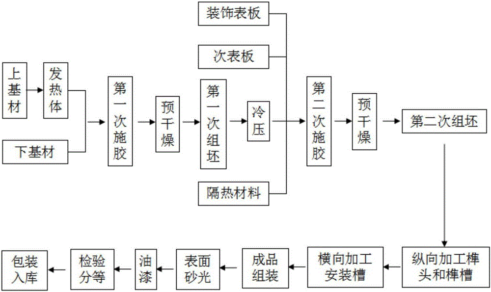
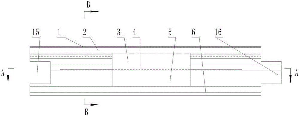
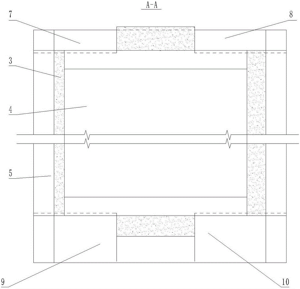
[0059] figure 2 , 3 , 4 and 10 represent a specific embodiment of the self-heating solid wood composite floor provided by the present invention, which mainly consists of decorative surface board 1, sub-surface board 2, upper base material 3, heating element 4, lower base material 5, heat insulation Material 6, electrical connection tenon groove 11, electrical connection tenon 12 and electrical connection conductor 13 etc. are formed, and it is processed by following technical scheme.

[0060] First of all, according to the market floor specifications, the decorative surface plate 1, the secondary surface plate 2, the upper base material 3, the heating element 4, the lower base material 5, and the heat insulation material 6 are processed into the required size, and the electrical connection is processed according to the requirements. Morti...


PUM


Abstract

The invention provides a safe and rapid circuit connecting structure and method for a heating floor. By means of the safe and rapid circuit connecting structure and method, circuit connection is reliable, high-charge zones are avoided, installation is convenient, the quality is stable, and safety and environmental friendliness are achieved. A heating body is arranged inside the heating floor, and power connection tenon mounting grooves and power connection mortise mounting grooves are formed in the two ends of the floor; conductive parts are exposed out of the bottom faces of the mounting grooves; a first conductive sleeve and a second conductive sleeve are arranged in the middle of each power connection tenon made of insulating materials and the middle of each power connection mortise made of insulating materials correspondingly; the power connection tenons and the power connection mortises are embedded into the power connection tenon mounting grooves and the power connection mortise mounting grooves correspondingly, and the first conductive sleeves and the second conductive sleeves make contact with the heating body exposed out of the bottom faces of the mounting grooves correspondingly; and the power connection tenons and the power connection mortises are provided with matched tenon-mortise structures, and when two floors are spliced, the power connection tenons on one floor can be connected with the power connection mortises on the other floor through the tenon-mortise structures, and a power connection conductor can be inserted into the first conductive sleeves and the second conductive sleeves to connect the conductive parts on the two floors.

Description

technical field [0001] The invention relates to a circuit connection structure of a heating floor and a connection method thereof, belonging to the field of floor heating floor manufacturing. Background technique [0002] Heating floor is one of the high-tech wooden products that have appeared in recent years. It can radiate heat evenly from the surface to the room. According to the air flow law of "cold drop and heat rise", the indoor heating effect can be achieved, and it is different from the traditional heating method. Compared with the geothermal floor, it is easier to arrange and look beautiful in the room, and it is more scientific and energy-saving. Therefore, the adoption of heating floor heating is recognized and accepted by more and more people, especially those without central heating facilities. [0003] However, the heating floor is still in the research stage and has not been substantially promoted in the market. The reason is that there are many deficiencie...

Claims


Application Information

Patent Timeline
IPC IPC(8): E04F15/02H01R31/06H01R13/04H01R13/10F24D13/02
CPCH01R13/04H01R13/10H01R31/06F24D13/024E04F15/02E04F15/02038E04F2290/023
Inventor 周兆兵郭晓磊丁建文曹平祥薛宏李想
Owner NANJING FORESTRY UNIV
Why Eureka
Try Eureka