A well-testing method for unstable wellhead pressure drop after acid fracturing

An acid fracturing and well testing technology, applied in wellbore/well components, measurement, earth-moving drilling and production, etc., can solve the problems of unstable well testing technical effect, long testing period, high testing cost, and reduce the risk of testing construction , The effect of saving test capital costs and saving test costs

Active Publication Date: 2020-03-27
程汉列
View PDF2 Cites 0 Cited by
  • Summary
  • Abstract
  • Description
  • Claims
  • Application Information

AI Technical Summary

Problems solved by technology

Shut in well for pressure recovery test, severely impacting production
[0010] ③. Steel wires or cables must be used to put high-precision storage or direct-reading electronic pressure gauges into the wellbore
The test tool string and electronic pressure gauge are kept in the pipe string during the test process. If corrosive fluid is produced in the wellbore, it will cause damage to the tool string and electronic pressure gauge
[0011] ④, Long test period, including flow pressure monitoring and pressure recovery monitoring
This will lead to an increase in testing costs. At the same time, due to the complex conditions in many wells, the tool strings running into the wells are often blocked or stuck, causing the tool strings to fall into the well, resulting in fish falling, which seriously affects the normal production and maintenance in the later stage.
[0015] ②, Long test period, including flow pressure monitoring and pressure drop monitoring
The whole test takes a long time and the test cost is high
[0016] CN201110208804 discloses a well test analysis method for pressure drop of shut-in wells in low-permeability reservoirs, but its effect on unstable well test techniques is not satisfactory

Method used


Image

  • A well-testing method for unstable wellhead pressure drop after acid fracturing
  • A well-testing method for unstable wellhead pressure drop after acid fracturing
  • A well-testing method for unstable wellhead pressure drop after acid fracturing

Examples


Embodiment 1

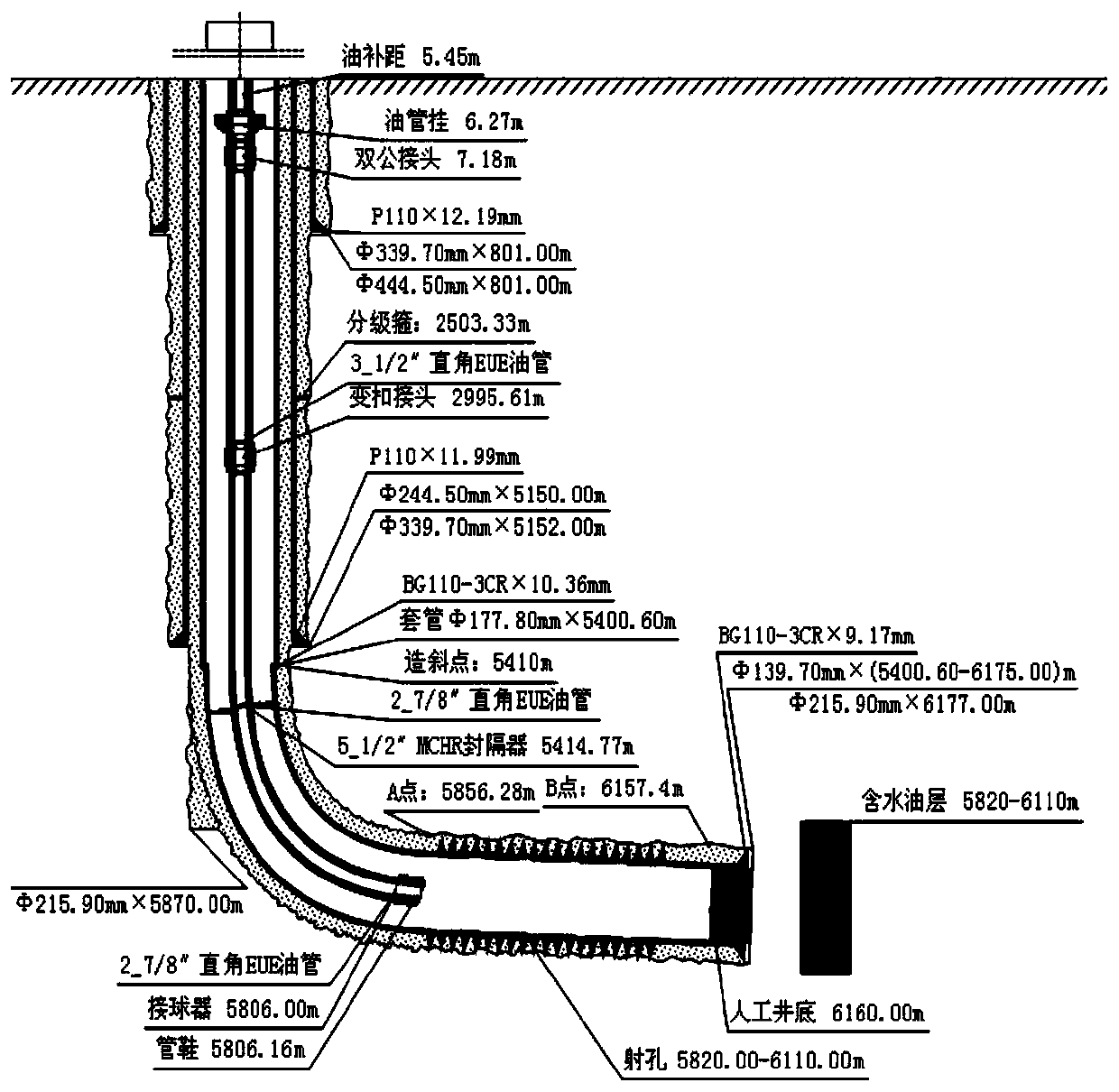
[0082] Geological overview of this example: the selected pressure drop test well is DH1-1GH, the well is a gas injection well, and the structural location is the Donghe No. 1 anticline in the Donghetang fault anticline zone of the Tabei uplift in the Tarim Basin. Casing, the drilled horizon is Carboniferous Donghe sandstone.

[0083] A well test method for unstable pressure drop at the wellhead after stopping the pump after acid fracturing, comprising the following steps:

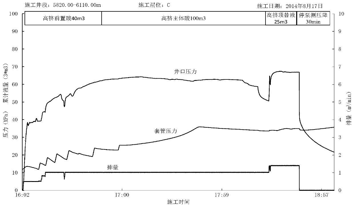
[0084] 1. During the acid fracturing process, install high-precision high-temperature and high-pressure storage or direct-reading electronic pressure gauges at the wellhead to record the wellhead pressure and casing pressure data. The data must include the pump pressure drop data at the wellhead when the pump is stopped. And draw the acidizing fracturing construction curve ( figure 1 ).

[0085] 2. Use the flowmeter to collect and record the displacement data of different fluids injected into the wellbore...


PUM


Abstract

The invention relates to a pump stopping wellhead pressure drop measuring transient well test method after acid fracturing. The method comprises the following steps that (1) pressure data in the whole acid fracturing process are recorded; (2) different fluid displacement data are recorded; (3) a well depth structure and the productive section well diameter are obtained; (4) frictional resistance is obtained; (5) well bottom pressure data in the whole acid fracturing process are simulated; (6) the effective reservoir thickness is gained; (7) the weighted porosity of the effective reservoir porosity is gained; (8) a rock compressibility coefficient is gained; (9) the formation pressure is converted, and the well bottom formation temperature is gained; (10) water saturation is obtained; (11) a water injection pressure drop transient well test analysis model is established; (12) all relevant parameter of the selected analytic model are obtained; and (13) all the parameters are obtained for reservoir evaluation. Through the method, the formation parameters are effectively obtained for reservoir evaluation. The test cost is reduced, the test construction risks are reduced, the individual well yield is not influenced, and the dynamic test data gaining rate is increased.

Description

technical field [0001] The invention belongs to the technical field of petroleum, and relates to a method for testing wells with unstable pressure drop at the wellhead after stopping pumps after acidizing and fracturing. Background technique [0002] The existing unstable well testing techniques include two types: [0003] ①. One is the unstable well test for pressure recovery. After the oil and gas well has been put into production for a period of time, a high-precision storage or direct-reading electronic pressure gauge is put into the bottom of the well by using a steel wire well test winch or a cable well test winch, and the well is in the production state. After monitoring the flowing pressure of the bottom hole pressure gauge measurement point for a certain period of time, the well is shut down on the surface or downhole, and the pressure recovery data of the bottom hole pressure gauge measurement point after the well shutdown is recorded, and combined with the product...

Claims


Application Information

Patent Timeline
Patent Type & Authority Patents(China)
IPC IPC(8): E21B47/06
CPCE21B47/06
Inventor 程汉列
Owner 程汉列
Why Eureka
Try Eureka