Electrochemical corrosion test apparatus and application method thereof

A test device, electrochemical technology, applied in the direction of measuring device, weather resistance/light resistance/corrosion resistance, material analysis using acoustic emission technology, etc., can solve the problem of inability to simulate acoustic emission detection and electrochemical detection, and inability to test tiny samples , the size of the tested sample is large, etc.

Active Publication Date: 2017-03-22
TIANJIN UNIV
View PDF6 Cites 14 Cited by
  • Summary
  • Abstract
  • Description
  • Claims
  • Application Information

AI Technical Summary

Problems solved by technology

The main disadvantages of existing test devices that use both acoustic emission technology and electrochemical technology to detect material corrosion properties are: (1) The size of the tested sample required by the traditional test device is too large, and it is impossible to test tiny samples
Welded joints are usually the weakest link in structural parts. If you want to perform acoustic emission and electrochemical detection on different areas of welded joints (weld root, cover surface, weld center, high temperature and low temperature thermal influence, etc.), based on sampling (2) In order to facilitate the installation of the acoustic emission sensor, the sample to be tested usually needs to be installed at the bottom of the electrolytic cell as a working electrode, so the existing test device limits the ability of the corrosive medium Heating and heat preservation; (3) Acoustic emission testing and electrochemical testing that cannot simulate the corrosion performance of materials in a variety of mixed gas environments; (4) The operation of sample installation and removal is complicated

Method used


Image

  • Electrochemical corrosion test apparatus and application method thereof
  • Electrochemical corrosion test apparatus and application method thereof
  • Electrochemical corrosion test apparatus and application method thereof

Examples


Embodiment Construction

[0087] The present invention will be further explained below in conjunction with the drawings and embodiments, but it should not be understood as a limitation to the present invention.

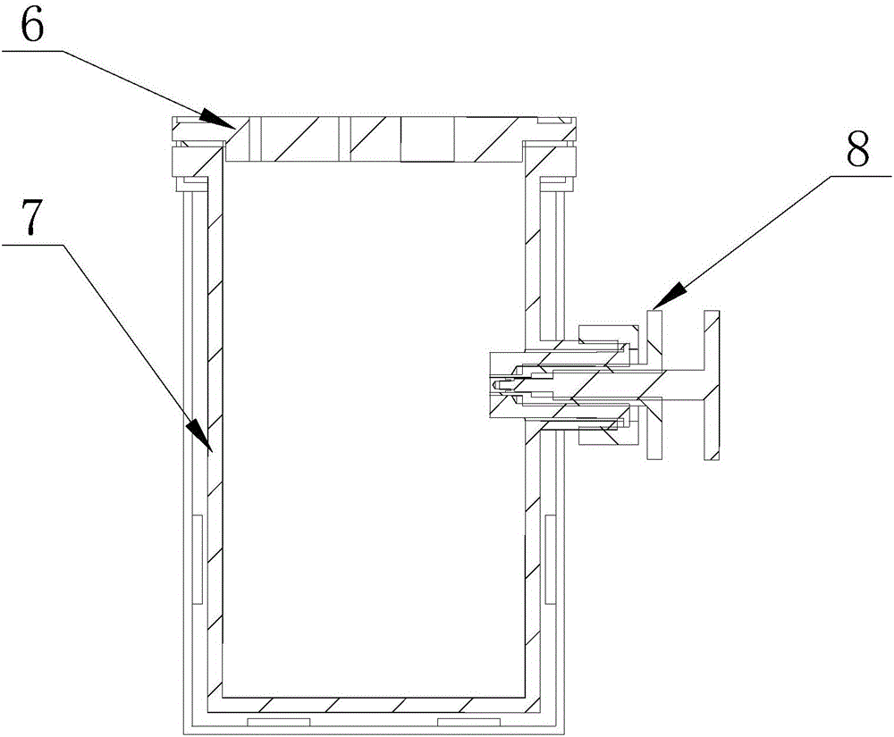
[0088] The sample fixture used for electrochemical corrosion test, namely the above attachment Figure 8 The sample mounting device in, consists of a stepped threaded waveguide rod, a first-stage sleeve, a second-stage sleeve, a third-stage sleeve and a sealing ring. The stepped-threaded waveguide rod, a first-stage sleeve, a second-stage sleeve, and a third-stage sleeve The barrel and the sealing ring are coaxially arranged, wherein: the stepped threaded waveguide rod is provided with a first external thread and a second external thread, and the first external thread is connected with the internal thread of the first-level sleeve so that the front end of the stepped threaded waveguide rod is placed In the first cavity and the second cavity of the first-level sleeve, the second external thread is ...


PUM

PropertyMeasurementUnit
diameteraaaaaaaaaa
diameteraaaaaaaaaa
lengthaaaaaaaaaa

Abstract

The invention discloses an electrochemical corrosion test apparatus and an application method thereof; the apparatus comprises an electrolytic cell, an electrochemical test device, a heating device and a thermal insulation device; the electrolytic cell comprises a reaction cell, a reaction cell cover, a seal gasket, a fastening device, and a sample mounting device; the sample mounting device comprises a step threaded waveguide rod, a primary sleeve, a secondary sleeve, a tertiary sleeve and a seal ring; the electrochemical test device comprises an auxiliary electrode chuck, a reference electrode chuck, a working electrode chuck, and an electrochemical data processing system; the auxiliary electrode is a platinum gauze electrode, the reference electrode is mounted in a Luggin-Haber capillary, the heating device is arranged outside the reaction cell, and the thermal insulation device is arranged outside the heating device. A corrosion process of a material in various complex corrosive gas environments can be simulated, a distance from the tip of the Luggin-Haber capillary to a test sample is fixed, the influences of the distance from the tip of the Luggin-Haber capillary to the test sample upon test results are uniformized, and the apparatus is suitable for use under severe complex conditions.

Description

Technical field [0001] The invention relates to the field of material corrosion performance testing, in particular to a corrosion electrochemical testing device and a use method thereof. Background technique [0002] Corrosion is a slow damage process of materials in a harsh service environment. It has the characteristics of strong concealment, accidental, sudden and severe destructiveness. Electrochemistry is a commonly used test method to quickly evaluate the corrosion resistance of materials, such as potentiodynamic polarization, potentiostatic polarization, cyclic potential polarization, electrochemical impedance testing, etc. Electrochemical technology is mainly aimed at the destructive testing of small samples, with the purpose of pre-predicting or post-evaluating the corrosion resistance of materials, but it is not possible to conduct online testing of the corrosion status of large components in service. Acoustic emission technology is a highly sensitive online non-destru...

Claims


Application Information

Patent Timeline
Patent Type & Authority Applications(China)
IPC IPC(8): G01N17/02G01N29/14
CPCG01N17/02G01N29/14G01N2291/023
Inventor 徐连勇张志强韩永典荆洪阳赵雷
Owner TIANJIN UNIV
Why Eureka
Try Eureka