
Self-calibrating method and system for laser-induced-fluorescence-based speed measurement

A laser-induced fluorescence and self-calibration technology, which is applied in the field of laser-induced fluorescence velocimetry self-calibration methods and systems, can solve the problems of limited measurement accuracy and high measurement cost, and achieve high detection accuracy, improved measurement accuracy, and clever ideas.

Active Publication Date: 2017-03-22
NAT UNIV OF DEFENSE TECH
View PDF4 Cites 9 Cited by
  • Summary
  • Abstract
  • Description
  • Claims
  • Application Information

AI Technical Summary

Problems solved by technology

[0005] The present invention provides a self-calibration method and system for laser-induced fluorescence velocimetry to solve the problem of high measurement cost and low measurement accuracy caused by using the element lamp method to calibrate the laser frequency corresponding to the absolute velocity zero point in the existing laser-induced fluorescence velocimetry. limited technical issues

Method used


Image

  • Self-calibrating method and system for laser-induced-fluorescence-based speed measurement
  • Self-calibrating method and system for laser-induced-fluorescence-based speed measurement
  • Self-calibrating method and system for laser-induced-fluorescence-based speed measurement

Examples


Embodiment Construction

[0031] It should be noted that, in the case of no conflict, the embodiments in the present application and the features in the embodiments can be combined with each other. The present invention will be described in detail below with reference to the accompanying drawings and examples.

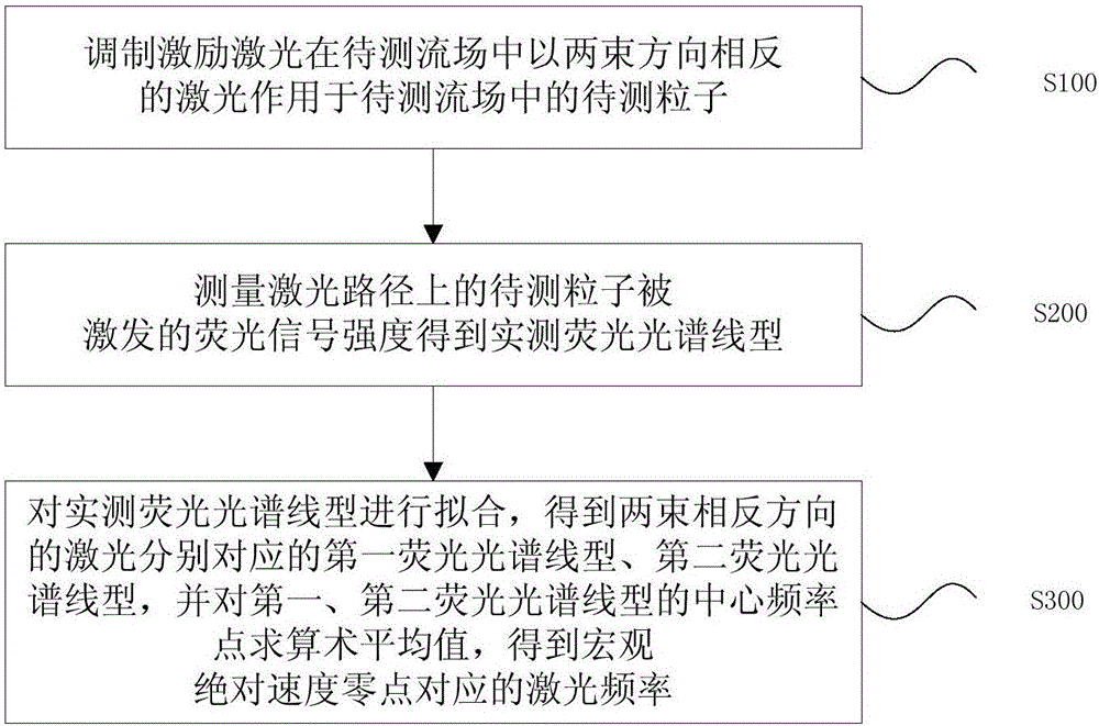
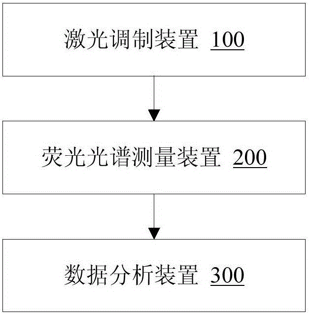
[0032] Aiming at the problems of high measurement cost and limited measurement accuracy caused by using the element lamp method to calibrate the laser frequency corresponding to the absolute velocity zero point in the existing laser-induced fluorescence velocimetry, the embodiment of the present invention provides a laser-induced fluorescence velocimetry The self-calibration method is used to calibrate the laser frequency corresponding to the absolute velocity zero point of the flow field to be measured in laser-induced fluorescence velocimetry. figure 1 , the self-calibration method of this embodiment includes:

[0033] Step S100, modulating the excitation laser to act on the particles to be ...


PUM


Abstract

The invention discloses a self-calibrating method and system for laser-induced-fluorescence-based speed measurement. The self-calibrating method comprises: exiting laser is modulated to apply two beams of laser in opposite directions in a to-be-measured flow field to a to-be-measured particle in the to-be-measured flow field; the strength of a fluorescence signal from the excited to-be-measured flow field on the laser path is measured to obtain a practical-measuring fluorescence spectrum profile; and fitting is carried out on the practical-measuring fluorescence spectrum profile to obtain a first fluorescence spectrum profile and a second fluorescence spectrum profile that correspond to the two beams of laser in opposite directions and numerical average value solving is carried out on central frequency points of the first fluorescence spectrum profile and the second fluorescence spectrum profile to obtain a laser frequency corresponding to an absolute speed zero point. Therefore, in-situ calibration is realized; and separate construction of a reference plasma source is not required. The calibration plan is simplified and the measuring cost is saved; a measuring error caused by a Stark effect under the circumstance of unequal densities between the reference plasma source and a to-be-measured plasma can be eliminated; and the measuring precision is improved.

Description

technical field [0001] The invention relates to the field of flow field velocity measurement, in particular to a self-calibration method and system for laser-induced fluorescence velocity measurement. Background technique [0002] Using laser induced fluorescence (Laser induced fluorescence, LIF) to measure the Doppler effect of selected particles in the moving fluid, and then obtain the particle velocity distribution function of the target flow field, is a non-contact, high sensitivity, and high selectivity technology. It has a very broad application prospect in the technical field involving plasma diagnosis (material processing, flow control, space electric rocket propulsion). In order to obtain the absolute value of the measured speed, it is necessary to calibrate the zero point of the absolute speed during the LIF speed measurement, that is, to obtain the corresponding laser frequency when the absolute speed is zero. [0003] At present, the element lamp method is used ...

Claims


Application Information

Patent Timeline
IPC IPC(8): G01P5/26G01P21/02
CPCG01P5/26G01P21/025
Inventor 程谋森杨雄王墨戈李小康
Owner NAT UNIV OF DEFENSE TECH
Learn More