

Impedance measuring device and impedance measuring method
A measurement device and measurement method technology, applied in the direction of measurement device, measurement of resistance/reactance/impedance, measurement of electrical variables, etc., can solve problems such as difficulty, difficulty in removing noise, impedance value deviation, etc., to reduce measurement errors and stabilize measurement values. , rapid results
- Summary
- Abstract
- Description
- Claims
- Application Information
AI Technical Summary
Problems solved by technology
Method used
Image

Examples
Embodiment Construction
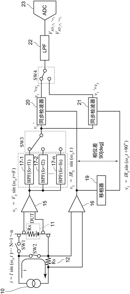
[0069] Embodiments of the present invention will be described below with reference to the drawings. figure 1 It is a schematic configuration diagram of the impedance measuring device according to the first embodiment of the present invention, and shows a connection configuration when measuring a noise component.
[0070] The constant current source 10 is connected to a sample (DUT: device under test) 11 to be measured via a switch SW1 . In this embodiment, sample 11 is a battery and has internal resistance Rx. A resistor (Rs) 12 for current detection is inserted into a series circuit of the constant current source 10 , the switch SW1 , and the sample 11 . The switch SW2 is inserted between the constant current source 10 and the switch SW1 , and between the sample 11 and the resistor 12 for current detection. The detection signal of the sample 11 is input to a plurality of band-pass filters (BPF) 17 via an amplifier 15 1 、17 2 , ......, 17 n middle. Switch SW3 selects th...
PUM
 Abstract
Description
Claims
Application Information