Artificial surface plasmon-based polarization sensor

A polarization sensor, localized surface plasmon technology, applied in the direction of electromagnetic field characteristics, etc., to achieve the effect of easy manufacturing, lower operating frequency, and a wide range of product applications

Inactive Publication Date: 2017-03-22
NANJING UNIV OF AERONAUTICS & ASTRONAUTICS
View PDF6 Cites 4 Cited by
  • Summary
  • Abstract
  • Description
  • Claims
  • Application Information

AI Technical Summary

Problems solved by technology

[0003] Technical problem: The technical problem to be solved by the present invention is: there are few existing special polarization sensor structure products, and a polarization sensor based on artificial surface plasmon polaritons is designed, which has simple structure, simple process, short cycle time and low cost

Method used


Image

  • Artificial surface plasmon-based polarization sensor
  • Artificial surface plasmon-based polarization sensor
  • Artificial surface plasmon-based polarization sensor

Examples


Embodiment 1

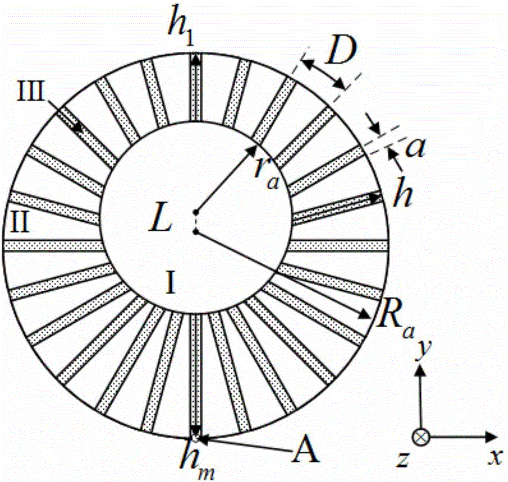
[0019] like figure 1 As shown, the basic structure of the sensor is a metal sheet with a thickness of 0.018 mm. The shape of the metal sheet is circular, and the thickness direction is defined as the z direction. A solid metal cylinder of equal height is distributed inside the metal sheet, and fan-shaped grooves with different depths (h) are evenly distributed along the outer circumferential direction of the metal sheet, and the grooves are filled with dielectric materials. Since the center of the inner cylinder does not coincide with the center of the entire structure, there is a distance L, resulting in unequal depths of the grooves. Along the direction from top to bottom, the depth of the groove gradually increases. Regions I and II in the figure are metal material parts, and region III is a groove part filled with dielectric materials. The radius of the outer cylinder is R a , the radius of the inner cylinder is r a , the shallowest and deepest groove depths are h 1 a...

Embodiment 2

[0021] as figure 1 The sensor shown is an example, the radius r a = 3 mm, R a = 10 mm, the radii of the shallowest and deepest grooves are h 1 = 5 mm, h m = 9 mm, the distance between the center of the entire structure and the center of the inner cylinder is L= 2 mm. The resonant frequencies of different groove depths are also different. The dielectric constant of the filling dielectric material is equal to 1, and a medium with a uniform dielectric constant can enhance the penetration of electromagnetic waves in the structure. The number of grooves is set to N=120.

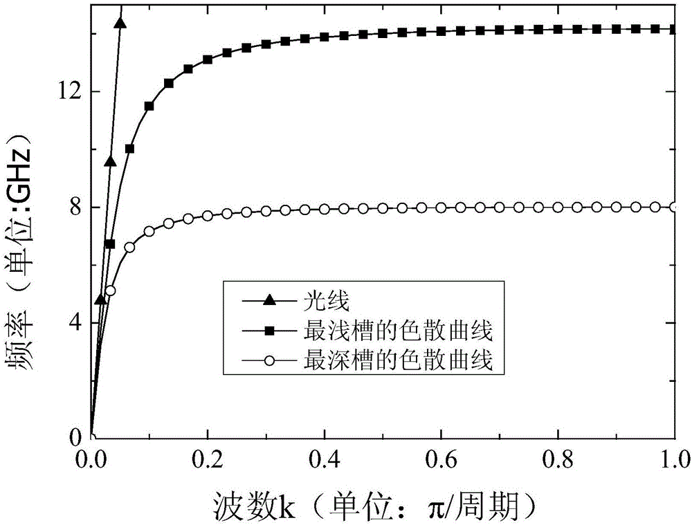
[0022] According to the second embodiment, for a single periodic structure with different groove depths, electromagnetic simulation software can be used to obtain the following figure 2 In the dispersion curve shown, the two curves correspond to the dispersion curves of the deepest groove and the shallowest groove respectively. It can be found that they are both located on the right side of the light, indic...

Embodiment 3

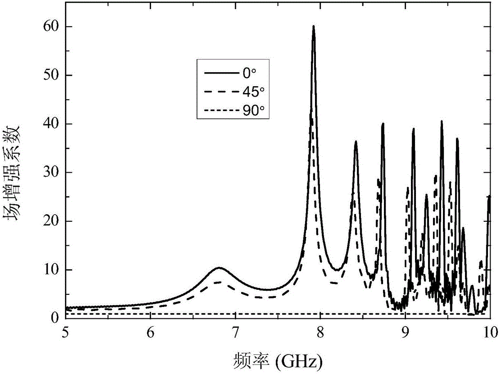
[0024] According to Embodiment 1, it is defined that the plane wave is incident along the +y direction to the -y direction, the wave vector is defined as the y direction, the electric field and the magnetic field are both in the xz plane, and the angle between the electric field component and the x axis is defined as θ, in A probe is set at position A at the bottom of the sensor structure 0.5 mm above the z direction. The probe can detect the electric field strength. The frequency band of the incident plane wave is 5 GHz to 10 GHz, and the electric field strength of the incident wave is 1 V / m. The ratio of the electric field strength detected by the probe to the electric field strength of the incident wave is defined as the field enhancement coefficient, image 3 It can be found that the field enhancement coefficient varies significantly with the angle θ in the entire frequency band, and the field enhancement gradually weakens with the increase of the angle θ. For the case whe...


PUM


Abstract

The present invention belongs to the metamaterial sensor technical field and provides a polarization sensor structure for realizing sensor functions in microwave low frequency bands, in particular an artificial surface plasmon-based polarization sensor. The artificial surface plasmon-based polarization sensor is characterized in that: subwavelength periodic trenches are formed in an ultra-thin metal cylindrical structure; the trenches are filled with dielectric materials; the dielectric constants of the materials are uniform; the depths of the trenches in the cylinder are different; the center of a cylindrical portion with no trenches formed inside does not overlap with the center of the structure of the whole cylinder; when electromagnetic waves enter the surface of the structure, a probe at one side of the structure can detect different field intensities for the electromagnetic waves which enter the structure from different directions, so that the function of the sensor can be realized. The sensor has the advantages of simple manufacture, low cost and high economic efficiency.

Description

technical field [0001] The invention relates to a polarization sensor structure, in particular to a polarization sensor based on artificial surface plasmons. Background technique [0002] In general, localized surface plasmon resonance refers to a localized electromagnetic wave mode bound on the metal surface, which is a resonance phenomenon of conduction electrons generated at the interface of positive and negative dielectric constants under the excitation of incident light. , generally confined near the metal-dielectric interface, can form an enhanced near-field effect. However, because the plasma frequency of metals is generally in the ultraviolet band, in the microwave band, electromagnetic waves are difficult to penetrate, and metals approximately behave as ideal conductors. Under these conditions, the metal surface cannot excite localized surface plasmons. In recent years, in order to introduce the concept of localized surface plasmons to low frequencies (far infrare...

Claims


Application Information

Patent Timeline
Patent Type & Authority Applications(China)
IPC IPC(8): G01R29/08
CPCG01R29/08
Inventor 李茁许秉正徐佳陈晨刘亮亮陈新蕾顾长青
Owner NANJING UNIV OF AERONAUTICS & ASTRONAUTICS
Why Eureka
Try Eureka