Imaging optical system

A technology of imaging optics and imaging surface, applied in optics, optical components, instruments, etc., can solve the problems of reducing the sense of substitution and realism of viewing images, insufficient clarity of peripheral field of view, and distortion of image display effects, etc., to increase the real experience , low distortion, increase the effect of substitution

Active Publication Date: 2017-03-22
JIAXING ZHONGRUN OPTICAL TECH
View PDF9 Cites 8 Cited by
  • Summary
  • Abstract
  • Description
  • Claims
  • Application Information

AI Technical Summary

Problems solved by technology

The human eye is more sensitive to TV distortion. Once the TV distortion is greater than 2%, it will make people feel that the picture is distorted.
Therefore, although the images obtained by many consumer products have a large field of view, which meets the needs of consumers to capture more comprehensive images, but at the same time, accompanied by large TV distortion, the display effect of the image is distorted and the viewing effect is reduced. The sense of substitution and realism in the image
[0007] 2. Poor image quality around the screen
At this time, the surrounding scenery squeezes together to occupy fewer pixels, resulting in insufficient clarity of the peripheral field of view.

Method used


Image

  • Imaging optical system
  • Imaging optical system
  • Imaging optical system

Examples


Embodiment Construction

[0038] The technical solution of the present invention will be further described below in conjunction with the accompanying drawings.

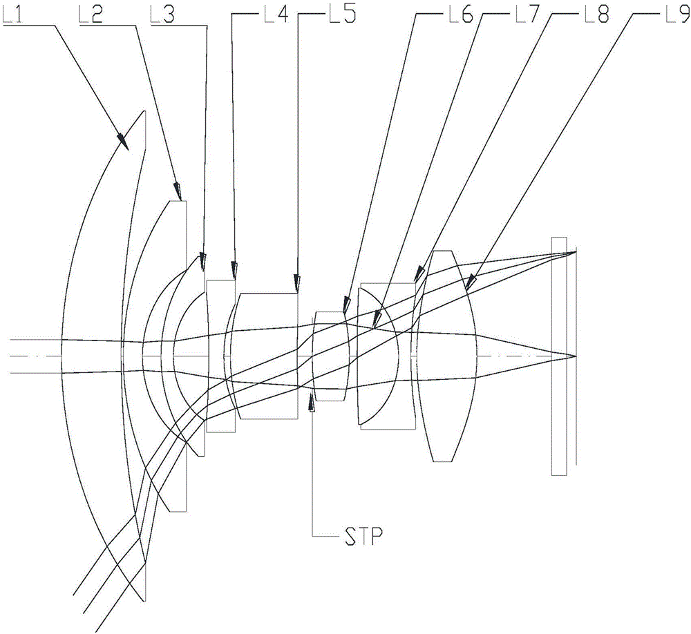
[0039] An imaging optical system, from the direction of the light incident scene to the imaging surface is set up in sequence:

[0040] The first lens group, from the direction of the light incident scene to the imaging surface, includes the first spherical lens L1, the second spherical lens L2, the third spherical lens L3, the fourth spherical lens L4, the fifth spherical lens L5; the stop STP; The second lens group includes a sixth spherical lens L6, a seventh spherical lens L7, an eighth spherical lens L8, a ninth aspheric lens L9, and an IR filter along the light incident direction.

[0041] The first spherical lens L1 has positive refractive power, the second, third and fourth spherical lenses all have negative refractive power, and the fifth spherical lens L5 has positive refractive power. The sixth spherical lens L6 has positive refrac...


PUM


Abstract

The invention provides an imaging optical system comprising a first lens group, a second lens group and a light filter which are arranged from a light incident scene direction to an imaging plane in turn. The first lens group comprises a first spherical lens, a second spherical lens, a third spherical lens, a fourth spherical lens and a fifth spherical lens which are arranged along the light incident direction. The second lens group comprises a sixth spherical lens, a seventh spherical lens, an eighth spherical lens and a ninth aspherical lens which are arranged along the light incident direction. The first spherical lens has positive focal power. The second spherical lens, the third spherical lens and the fourth spherical lens have negative focal power. The fifth spherical lens has the positive focal power. The sixth spherical lens has the positive focal power. The seventh spherical lens and the eighth spherical lens form a gluing piece and the whole body has the negative focal power. The ninth aspherical lens has the positive focal power.

Description

technical field [0001] The invention relates to an optical imaging system. Background technique [0002] In the field of sports DV and UAV aerial photography, it is necessary to use imaging optical system to capture images and shoot videos. Sports DV is generally fixed on the athlete's body or equipment, and is used to record the athlete's exercise state or surrounding environment when the athlete is active. For example, in skydiving, the sports DV is used to fix on the body of the skydivers, and is used to record the state of the surrounding skydivers and the scenery that can be watched during the skydiving. When this video is played again, it can make people feel immersive. In order to record as many surrounding images as possible, sports DV generally have a large field of view. When taking aerial photography with a UAV, it is also necessary to capture objects within as large an angle as possible. At the same time, in order to make the observed scenes closer to reality...

Claims


Application Information

Patent Timeline
Patent Type & Authority Applications(China)
IPC IPC(8): G02B13/06G02B13/18
CPCG02B13/06G02B13/18
Inventor 盛亚茗李长锋尚洁阳张平华
Owner JIAXING ZHONGRUN OPTICAL TECH
Why Eureka
Try Eureka