High stability fuel assembly compacting system with variable rigidity and low radiation slack

A fuel assembly, high-stability technology, applied in the field of compression systems, can solve the problems of easy irradiation relaxation, insufficient compression force, reduced spring compression force, etc., to reduce structural materials, reduce axial loads and stress levels , reduce the effect of bending deformation

Active Publication Date: 2017-03-22
NUCLEAR POWER INSTITUTE OF CHINA
View PDF5 Cites 8 Cited by
  • Summary
  • Abstract
  • Description
  • Claims
  • Application Information

AI Technical Summary

Problems solved by technology

[0005] The present invention mainly solves the problem that there is a large stress inside the spring when the existing pressing system is in operation, which leads to easy radiation relaxation, thereby reducing the pressing force of the spring, and the

Method used


Image

  • High stability fuel assembly compacting system with variable rigidity and low radiation slack
  • High stability fuel assembly compacting system with variable rigidity and low radiation slack
  • High stability fuel assembly compacting system with variable rigidity and low radiation slack

Examples


Embodiment 1

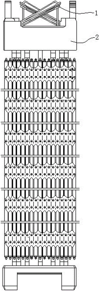
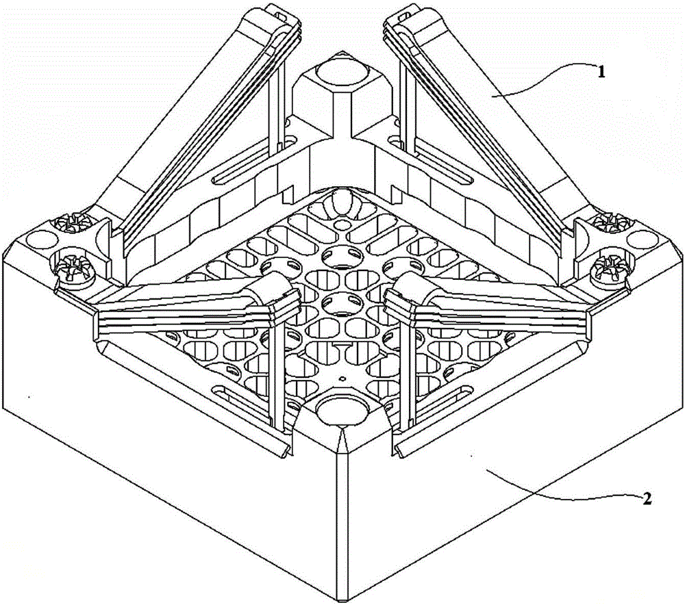
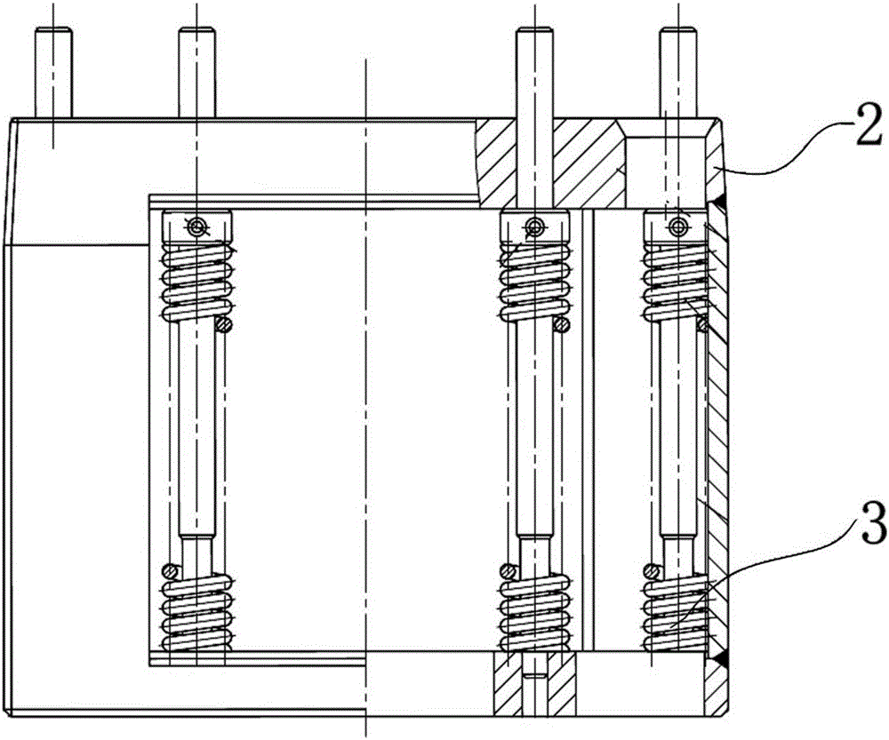
[0039] A high-stability fuel assembly compression system with variable stiffness and low radiation relaxation, such as figure 1 , figure 2 and image 3 As shown, it includes a leaf spring set 1 installed on the tube base 2 and a coil spring set 3 installed in the tube base 2 . In the present invention, the leaf spring assembly 1 is installed on the fuel assembly socket 2, which can be the upper socket at the upper end of the fuel assembly, or the lower socket at the lower end. In this embodiment, the above socket is taken as an example.

[0040] Such as figure 2 As shown, the leaf spring group 1 includes an A leaf spring 11 stacked from top to bottom and more than one B leaf spring 12. The A leaf spring 11 consists of a horizontal section, an inclined arm and a vertical The B plate spring is composed of a horizontal section and an inclined arm. The end of the inclined arm of the B plate spring is provided with a window for the vertical arm to pass through. The horizontal ...

Embodiment 2

[0049] The difference between this embodiment and Embodiment 1 is that this embodiment optimizes the structure of the helical spring group 3, and the specific settings are as follows:

[0050] The coil spring group 3 includes a compression rod 31 that runs through the tube base 2 , a compression cap 32 that is arranged on the compression rod 31 and is located at the top end of the tube base 2 , and is sleeved on the compression rod 31 and is located inside the tube base 2 . The spiral outer spring 33 below the pressure cap 32; the pressure rod 31 below the pressure cap 32 in the tube seat 2 is also provided with a step, and the preset inner spring 34 is arranged between the step and the pressure cap 32, and the preset inner The spring is located inside the helical outer spring 33 . In this embodiment, the preset inner spring 34 is a helical spring, such as Figure 5 shown.

Embodiment 3

[0052] The difference between this embodiment and Embodiment 2 is that the setting of the preset inner spring 34 in this embodiment is different, and the preset inner spring 34 is a disc spring in this embodiment, such as Figure 6 shown.


PUM


Abstract

The invention discloses a high stability fuel assembly compacting system with variable rigidity and low radiation slack. The system solves the problem that the existing compacting system has large stress in a spring in operation so that radiation slack is easy and a spring pressing force is reduced and is insufficient in the middle and late stages of the life of the fuel assembly. The system comprises a plurality of spring assemblies mounted on a tube socket (2) and is characterized in that a preset spring is arranged in the spring assembly, in a thermal state normal operation of the fuel assembly, the preset spring is in a natural state, and when the fuel assembly jumps under the transient external load or the burnup of the fuel assembly is increased, the preset spring is in a compacting state. The system reduces bending deformation during the operation of the fuel assembly and improves the fuel assembly running stability and the service life.

Description

technical field [0001] The invention relates to a pressing system, in particular to a high-stability fuel assembly pressing system with variable stiffness and low radiation relaxation. Background technique [0002] Existing reactor fuel assemblies usually consist of a number of fuel rods, guide tubes, spacer grids, lower tube base parts, and tube base parts containing a compression system, such as figure 1 shown. The compression system is arranged on the top of the fuel assembly, axially compresses the fuel assembly, keeps it in contact with the lower core plate, and compensates for the radiation growth of the fuel assembly and the thermal expansion difference of the fuel assembly relative to the internal components. [0003] The fuel assembly pressing system of the conventional technology is composed of several groups of spring groups symmetrically installed on the top of the pipe seat, such as figure 1 shown. Taking the leaf spring compression system as an example, the ...

Claims


Application Information

Patent Timeline
IPC IPC(8): G21C3/33
CPCG21C3/331Y02E30/30
Inventor 蒲曾坪张吉斌庞华齐敏陈平朱发文黄春兰李云陈杰
Owner NUCLEAR POWER INSTITUTE OF CHINA
Why Eureka
Try Eureka