Switching power supply converter control circuit and control method thereof

A switching power supply and control circuit technology, applied in the direction of adjusting electrical variables, controlling/regulating systems, converting DC power input to DC power output, etc. and other problems to achieve the effect of simplifying system settings

Active Publication Date: 2017-03-22
WUXI SI POWER MICRO ELECTRONICS
View PDF4 Cites 29 Cited by
  • Summary
  • Abstract
  • Description
  • Claims
  • Application Information

AI Technical Summary

Problems solved by technology

[0004] However, the existing primary-side sampling-modulated switching power supply is limited by problems such as constant current control and sub-harmonic oscillation, and can only work in DCM mode. In order to meet the minimum demagnetization time length under no-load conditions in the full voltage range, this Limits the operating frequency of the primary side sampling modulation switching power supply, which affects the power density of the switching power supply per unit volume
In addition, compared with the CCM mode, the primary and secondary peak currents of the DCM mode under the same output power condition are larger, and the loss of the power path is larger, which will affect the conversion efficiency of the switching power supply.

Method used


Image

  • Switching power supply converter control circuit and control method thereof
  • Switching power supply converter control circuit and control method thereof
  • Switching power supply converter control circuit and control method thereof

Examples


Embodiment Construction

[0035] The present invention will be further described below in conjunction with specific drawings.

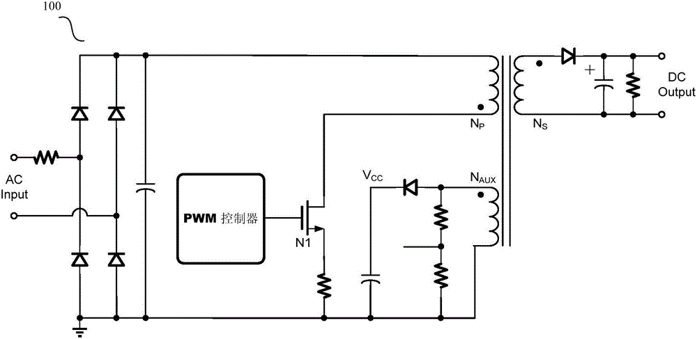
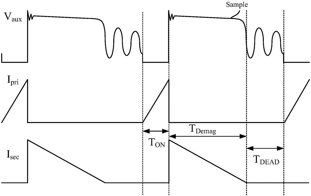
[0036] Such as figure 1 As shown, the flyback switching power supply system 100 is sampled on the primary side. The output voltage signal of the flyback switching power supply system 100 is sampled during the demagnetization process in each switching cycle. next switch action. Before the power transistor N1 is triggered each time, the demagnetization of the transformer is completed, and the current of the primary coil is zero, so the flyback switching power supply system 100 works in the DCM mode. This control process is relatively simple, and the constant current and constant voltage calculation of the loop can also be simplified, but this mode will limit the operating frequency of the switching power supply and affect the power density of the power supply system. According to the volt-second balance law:

[0037] V IN *T ON =N*V OUT *T OFF ;

[0038] Among them, V IN ...


PUM


Abstract

The present invention relates to a switching power supply converter control circuit and a control method thereof. The circuit comprises an output signal sampling and holding module, an error amplifier, a serrated signal generator, a PWM comparator, a demagnetization detection comparator, a timing module, a demagnetization time maintenance iteration module, a positive degree side median current sampling module, a constant current calculation module and a peak value current comparator. Through adoption of the coupling relation of the transformer secondary coil and the auxiliary coil, the output signal sampling and holding module samples the feedback signals showing the voltage of the secondary coil at the transformer demagnetization stage; the sampling signals and the standard voltage are amplified through the error amplifier, the output of the error amplifier and the serrated signals are modulated to generate PWM signals to control the conduction of the power tube; and at the power tube conduction stage, the pressure drop of the positive degree side power sampling resistor is larger than the threshold voltage calculated by a constant current loop, and the power tube is turned off. The switching power supply converter control circuit and the control method thereof allow the switching power supply worked in the CCM mode to realize the constant voltage function in various work modes.

Description

technical field [0001] The invention relates to a control circuit and a control method of a switching power converter, in particular to a control circuit and a control method of a flyback switching power converter, belonging to the technical field of integrated circuits. Background technique [0002] Flyback switching power supply is widely used because of its simple application structure and low cost. In a traditional flyback switching power supply, optocoupler devices and TL431 are usually used to isolate and sample the output voltage signal of the secondary side for loop modulation, which increases the system cost. In addition, cable voltage drops that vary with output current levels are often difficult to compensate. [0003] In order to reduce the system cost and size of the flyback switching power supply, the switching power supply using primary side sampling modulation is more and more widely used. In the primary side adjustment, through the coupling relationship be...

Claims


Application Information

Patent Timeline
Patent Type & Authority Applications(China)
IPC IPC(8): H02M7/217H02M3/335
CPCH02M3/33507H02M7/217Y02B70/10
Inventor 励晔黄飞明赵文遐吴霖朱勤为
Owner WUXI SI POWER MICRO ELECTRONICS
Why Eureka
Try Eureka