A kind of back cover of electronic equipment and back cover preparation method

A technology of electronic equipment and back cover, which is applied in the direction of casing/cabinet/drawer parts, metal casing, etc., can solve the problems of high cost, cumbersome processing process, weak overall strength of the back cover, etc., and achieve high mass production , low cost, stable size

Active Publication Date: 2019-10-15
VIVO MOBILE COMM CO LTD
View PDF8 Cites 0 Cited by
  • Summary
  • Abstract
  • Description
  • Claims
  • Application Information

AI Technical Summary

Problems solved by technology

[0004] The embodiment of the present invention provides a back cover of an electronic device and a preparation method for the back cover, so as to solve the problems of the existing manufacturing method that the processing process is relatively cumbersome, the cost is high, and the overall strength of the manufactured back cover is weak

Method used


Image

  • A kind of back cover of electronic equipment and back cover preparation method
  • A kind of back cover of electronic equipment and back cover preparation method
  • A kind of back cover of electronic equipment and back cover preparation method

Examples


Embodiment 1

[0024] The back cover provided in this embodiment can be applied to electronic equipment, which includes but not limited to mobile terminals, computers, televisions and other equipment.

[0025] refer to figure 1 , shows a schematic structural diagram of a rear cover of an electronic device in an embodiment of the present invention.

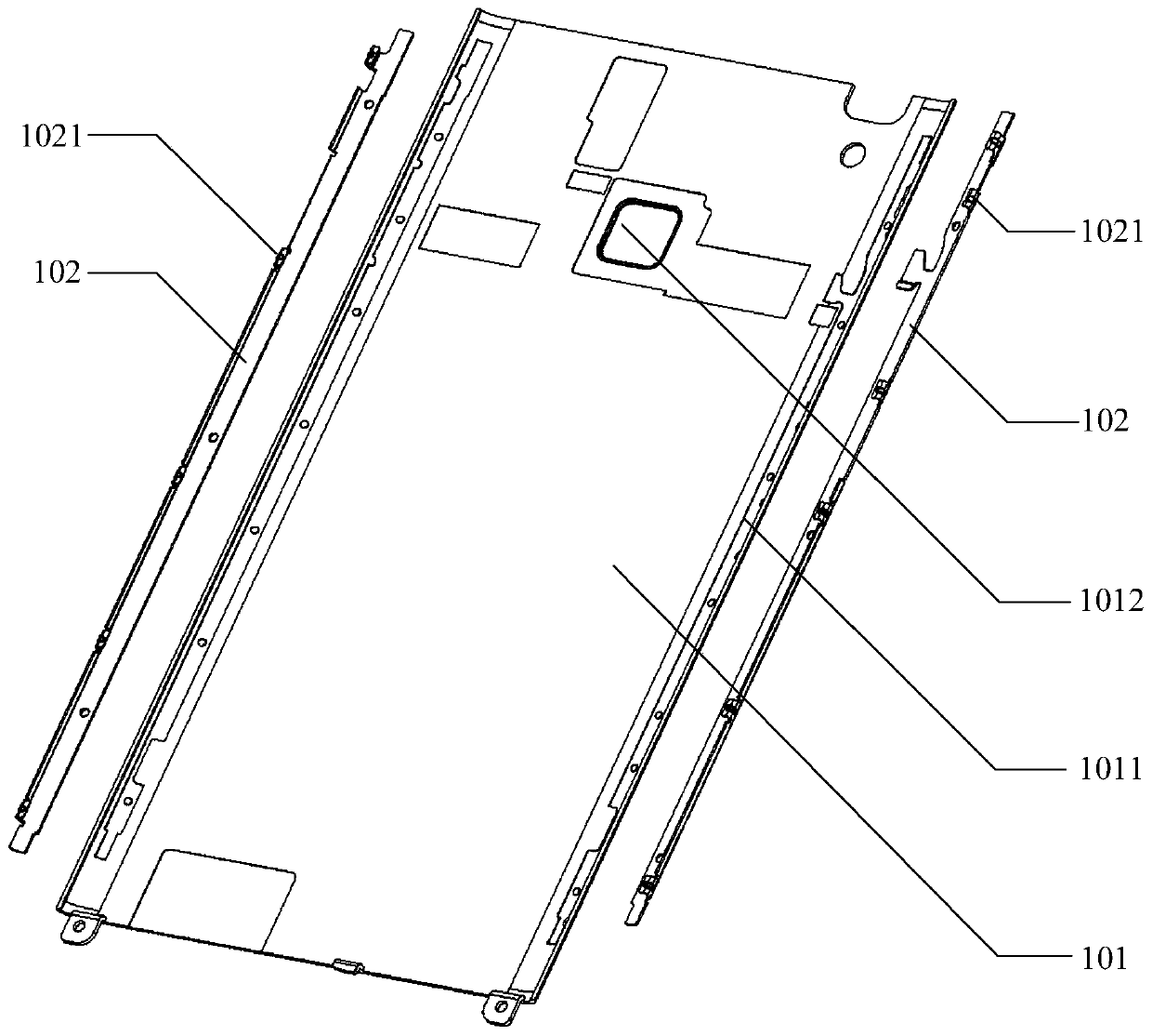
[0026] The back cover includes: a back cover body 101 and a buckle bracket 102 .

[0027] Wherein, the buckle bracket 102 includes a connection buckle 1021, and the connection buckle 1021 is used to connect the back cover to the device body of the electronic device. Specifically, the connecting buckle 1021 is buckled and connected with the buckle corresponding to the device body of the electronic device, so as to realize the assembly of the back cover and the body of the electronic device. For example, if the electronic device is a mobile phone, the back cover is the battery cover of the mobile phone, and the battery cover can be freely disasse...

Embodiment 2

[0034] refer to figure 2 , shows a schematic structural diagram of another electronic device back cover in an embodiment of the present invention, and the back cover provided in this embodiment is a preferred embodiment based on the first embodiment.

[0035] The back cover specifically includes: a back cover body 101 and a buckle bracket 102 . In this embodiment, the rear cover body 101 includes a glue overflow groove 1011 and a hole 1012 .

[0036] Wherein, the glue overflow groove 1011 is a groove formed by etching, located on the surface of the connecting end of the back cover body 101 and the buckle bracket 102, and the depth of the glue overflow groove 1011 depends on the thickness of the back cover body. When dispensing the back cover body 101 and the buckle bracket 102, the overflow groove 1011 can be used to limit the area covered by the hot melt glue, prevent the liquid hot melt glue in a high temperature state from overflowing during dispensing, and avoid non-conn...

Embodiment 3

[0044] An embodiment of the present invention provides an electronic device, which adopts the back cover described in the above embodiment. Then the electronic device includes a device body and a back cover, and the back cover is fastened on the device body.

[0045] The back cover includes: a back cover body and a buckle bracket.

[0046] Wherein, the buckle bracket includes a connection buckle, and the connection buckle is used to connect the back cover to the device body of the electronic device. Specifically, the connecting buckle is buckled and connected with the buckle corresponding to the device body of the electronic device, so as to realize the assembly of the back cover and the device body.

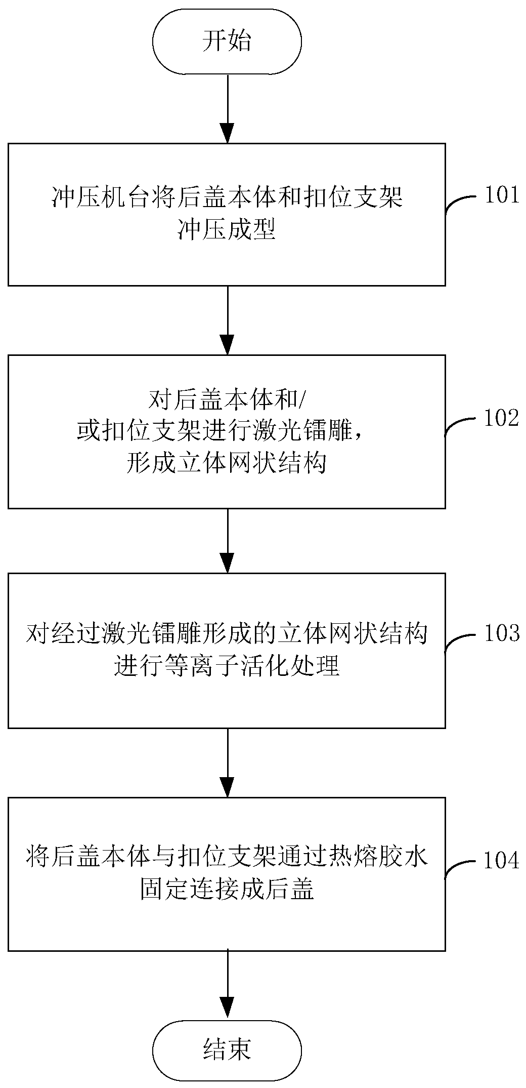
[0047] The back cover body and the buckle bracket are prepared separately and independently, so both the back cover body and the buckle bracket can be formed by stamping, and can be made of different metals.

[0048] After the back cover body and the buckle bracket are separat...


PUM


Abstract

The embodiment of the invention provides a rear cover of electronic equipment and a rear cover preparation method. The rear cover preparation method includes first performing punch forming of a rear cover body and a buckling support by a punching machine, then performing laser carving on the rear cover body and / or the buckling support, carving the surface of one end to be connected of the rear cover body and / or buckling support into a three-dimensional grid structure, and performing plasma activating treatment on the three-dimensional grid structure formed by laser carving to increase surface energy, so that the rear cover body and the buckling support are fixedly connected into a rear cover of electronic equipment through hot melting glue. Since both the rear cover body and the buckling support can be formed by punching, the rear cover preparation method has the characteristics of simple process, stable size, high productivity, low cost and the like. In addition, since two different metals can be adopted to realize combination through glue dispensing, the rear cover can have the advantages of the different metals at the same time.

Description

technical field [0001] The embodiments of the present invention relate to the technical field of mechanical engineering, and in particular to a method for preparing a structural part. Background technique [0002] In the technical field of mechanical engineering, a structural member refers to a component that has a certain shape and structure and can bear loads. For example, the back cover of an electronic device is a typical structural component, and the back cover of the electronic device is fixed to the device body of the electronic device through buckles. [0003] The traditional manufacturing method of structural parts is usually to perform multiple CNC (Computer Numerical Control, computer numerical control machine tool) processing on the metal plate to obtain the characteristic structure of the required structural parts and the corresponding structural part products. Although CNC processing has the advantages of high precision and good stability, it takes a lot of ti...

Claims


Application Information

Patent Timeline
Patent Type & Authority Patents(China)
IPC IPC(8): H05K5/03H05K5/04B23P15/00
Inventor 张道黄克
Owner VIVO MOBILE COMM CO LTD
Why Eureka
Try Eureka