Minitype blade-free type turbine
A micro-turbine, turbine technology, applied in non-variable-capacity engines, mechanical equipment, engine components, etc., can solve the problems of complex blade structure, high manufacturing requirements, and difficult maintenance, and achieve low material and technical requirements and simple structure. Effect
- Summary
- Abstract
- Description
- Claims
- Application Information
AI Technical Summary
Problems solved by technology
Method used
Image

Examples
Embodiment Construction
[0024] The present invention will be described in detail below with reference to the accompanying drawings and examples.
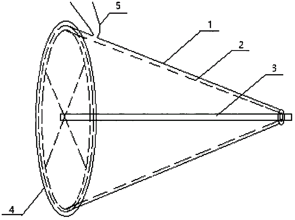
[0025] The present invention provides a miniature bladeless turbine, see attached figure 1 , including: outer sleeve 1, inner sleeve 2, rotor shaft 3, intake nozzle 4, sealing sleeve 5;
[0026] See attached figure 1 , the gas enters between the outer sleeve 1 and the inner sleeve 2 through the air inlet nozzle 4, and drives the inner sleeve 2 to rotate. The inner sleeve 2 is just connected to the rotor shaft 3, and the rotor shaft 3 can perform external work. The gas rotates in the turbine, and as the kinetic energy decreases, the radius of rotation decreases until the gas exits the turbine.
[0027] The sealing sleeve 5 seals the outer sleeve of the air intake end to prevent air leakage at the air intake end.
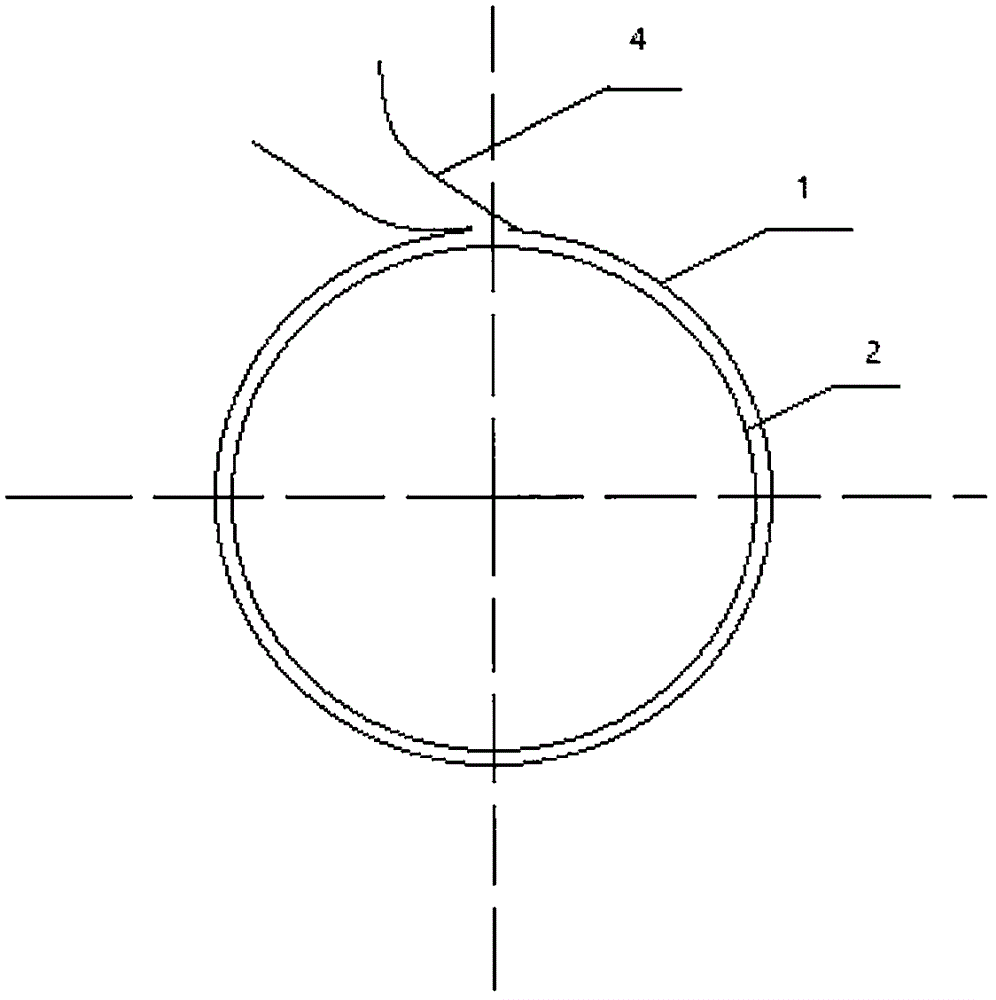
[0028] See attached figure 2 , is the sectional view of the intake port, the gas enters the turbine from the intake nozzle 4. A microturbin...
PUM
 Abstract
Description
Claims
Application Information
 - R&D
- Intellectual Property
- Life Sciences
- Materials
- Tech Scout
- Unparalleled Data Quality
- Higher Quality Content
- 60% Fewer Hallucinations
Browse by: Latest US Patents, China's latest patents, Technical Efficacy Thesaurus, Application Domain, Technology Topic, Popular Technical Reports.
© 2025 PatSnap. All rights reserved.Legal|Privacy policy|Modern Slavery Act Transparency Statement|Sitemap|About US| Contact US: help@patsnap.com