
Silencer of internal combustion engine

A muffler and internal combustion engine technology, applied in the direction of machines/engines, mufflers, mechanical equipment, etc., can solve the problems that the muffler does not have high temperature resistance, affects the service life of the muffler, and the muffler effect is not obvious, so as to achieve a good muffler effect , Simple structure and convenient installation

Inactive Publication Date: 2017-03-29
湖州山海环保工程有限公司
View PDF7 Cites 2 Cited by
  • Summary
  • Abstract
  • Description
  • Claims
  • Application Information

AI Technical Summary

Problems solved by technology

[0002] The so-called muffler, a muffler is a device that allows airflow to pass through, but can prevent or reduce sound transmission. It is an important measure to eliminate aerodynamic noise. The muffler can block the transmission of sound waves and allow airflow to pass through. It is an effective tool for noise control , with the development of science and technology, the scope of application of muffler technology is becoming wider and wider, which involves a muffler for internal combustion engines. The internal combustion engine will generate exhaust gas during operation. If the exhaust gas is discharged directly, it will produce a lot of noise and affect Therefore, the user usually needs to install a muffler. Since the temperature of the exhaust gas generated by the internal combustion engine is relatively high, the general muffler does not have the characteristics of high temperature resistance, which affects the service life of the muffler, and the effect of muffler is not obvious.

Method used


Image

  • Silencer of internal combustion engine
  • Silencer of internal combustion engine
  • Silencer of internal combustion engine

Examples


Embodiment Construction

[0015] The following will clearly and completely describe the technical solutions in the embodiments of the present invention with reference to the accompanying drawings in the embodiments of the present invention. Obviously, the described embodiments are only some, not all, embodiments of the present invention. Based on the embodiments of the present invention, all other embodiments obtained by persons of ordinary skill in the art without making creative efforts belong to the protection scope of the present invention.

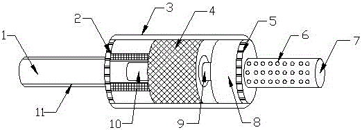
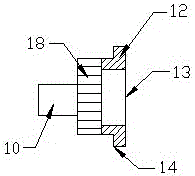
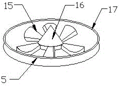
[0016] see Figure 1-3 The present invention provides a technical solution: a muffler for an internal combustion engine, comprising a muffler main body 1 and a muffler cavity 4 arranged inside the muffler main body 1, an exhaust main pipe 11 is installed at one end of the muffler main body 1, and the exhaust One end of the gas main pipe 11 is connected with a muffler sound insulation board 2 made of high temperature resistant material, the other end of the muf...


PUM


Abstract

The invention discloses a silencer of an internal combustion engine. The silencer comprises a silencer main body and a noise elimination chamber disposed inside the silencer main body, wherein an exhaust manifold is installed on one end of the silencer main body; one end of the exhaust manifold is connected to a silencer sound insulation plate made of a heat-resisting material; the other end of the silencer main body is equipped with an exhaust end; a wind guide fan is installed on one side of the exhaust end; a wind guide fan outer cover is disposed on one side of the wind guide fan; a wind guide cone is disposed at the middle part of the wind guide fan outer cover; multiple wind guide blades are installed around the wind guide cone; an inflow pipe section is installed inside the silencer main body; a noise elimination cylinder is disposed inside the noise elimination chamber; the inflow pipe section is connected to one end of the noise elimination cylinder; the other end of the noise elimination cylinder is connected to a noise elimination bowl; a U-shaped wave solenoid is disposed on one side of the noise elimination chamber; and an outflow pipe section is disposed between the U-shaped wave solenoid and the sound elimination chamber. The silencer of the internal combustion engine is characterized by rapid heat dissipation, a long service life, a simple structure, good noise elimination results, convenient installation, etc.

Description

technical field [0001] The invention relates to the technical field of mufflers, in particular to a muffler for an internal combustion engine. Background technique [0002] The so-called muffler, a muffler is a device that allows airflow to pass through, but can prevent or reduce sound transmission. It is an important measure to eliminate aerodynamic noise. The muffler can block the transmission of sound waves and allow airflow to pass through. It is an effective tool for noise control , with the development of science and technology, the scope of application of muffler technology is becoming wider and wider, which involves a muffler for internal combustion engines. The internal combustion engine will generate exhaust gas during operation. If the exhaust gas is discharged directly, it will produce a lot of noise and affect Therefore, the user usually needs to install a muffler. Because the temperature of the exhaust gas generated by the internal combustion engine is relative...

Claims


Application Information

Patent Timeline
Patent Type & Authority Applications(China)
IPC IPC(8): F01N13/00
CPCF01N13/007
Inventor 胡航海谢建胡谦
Owner 湖州山海环保工程有限公司
Learn More