
Vacuum arc thruster, multi-mode structure and multi-mode achieving manners

A thruster and vacuum arc technology, which is applied in the field of vacuum arc thrusters, can solve the problems of difficulty in meeting satellite propulsion requirements and single working mode, and achieve the effects of reducing space charge effects, reducing plume divergence angle, and improving efficiency

Inactive Publication Date: 2017-03-29
LANZHOU INST OF PHYSICS CHINESE ACADEMY OF SPACE TECH
View PDF3 Cites 12 Cited by
  • Summary
  • Abstract
  • Description
  • Claims
  • Application Information

AI Technical Summary

Problems solved by technology

The propulsion functions performed mainly include tasks such as position maintenance and orbit maneuvering. The current coaxial vacuum arc thrusters have a single working mode at a fixed frequency, and it is difficult to meet the different propulsion needs of satellites.

Method used


Image

  • Vacuum arc thruster, multi-mode structure and multi-mode achieving manners
  • Vacuum arc thruster, multi-mode structure and multi-mode achieving manners
  • Vacuum arc thruster, multi-mode structure and multi-mode achieving manners

Examples


Embodiment 1

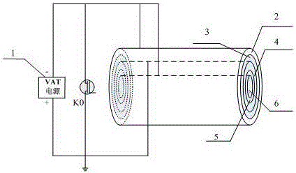
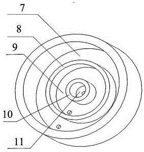
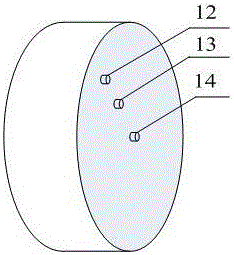
[0016] Embodiment 1, with reference to figure 1 , 2 3. A vacuum arc thruster, which includes a central cylindrical cathode 6 (the cylindrical cathode can make the ablation of the cathode uniform, which is beneficial to increase the life of the thruster), and the outer circumference of the cylindrical cathode 6 is concentric Set the insulator II5, the common anode 4, the insulator I3 and the outer ring cathode 2; the cylindrical cathode 6, the insulator II5, the common anode 4, the insulator I3 and the outer ring cathode 2 are sequentially installed on the cylindrical cathode of the installation base In the installation groove 11, the insulator II installation seat 10, the common anode installation groove 9, the insulator I installation seat 8 and the outer ring cathode installation groove 7; the outer end surface of the installation base is sequentially provided with cylindrical cathode terminals from the center to the outside 14. The common anode terminal 13 and the outer ri...

Embodiment 2

[0017] Embodiment 2, embodiment 2, on the basis of embodiment 1, insulator rings and cathode rings are sequentially added as required to form a vacuum arc thruster with a multi-ring structure, so as to expand the power of the thruster and expand the application range of the thruster.

[0018] When the thruster is working, the voltage peak generated by the power processing unit breaks down the metal conductive films on the end faces of the two insulators at the same time, inducing the main discharge between the cathode and anode of the two groups. The resulting plasma ions are accelerated by mechanisms such as aerodynamics and electron-ion friction to generate thrust.

Embodiment 3

[0019] Embodiment 3, with reference to Figure 4 , a multi-mode structure of a vacuum arc thruster is obtained on the basis of Example 1. The negative pole of the power supply 1 is connected in parallel with inductors L1 and L2 controlled by switches K1 and K2 respectively. The other ends of the inductors L1 and L2 are respectively connected to switches K0, switches K3, switches K5, switches K7, Switch K8, while the other end of switch K0 is grounded, the other end of switch K3, switch K8 is connected to cathode 6, the other end of switch K5, switch K7 is connected to outer ring cathode 2; one end of switch K4, switch K6, and switch K9 are connected together Common anode 4, and the other end of switch K4, switch K6, switch K9 connects the positive pole of power supply 1 together.

[0020] Under the above structure, the thruster has a total of 6 working modes at a fixed frequency, and different working modes correspond to different power and thrust. Specifically: when the ind...


PUM


Abstract

The invention discloses a vacuum arc thruster. The thruster comprises a cathode located in the center. An insulator II, a common anode, an insulator I and an outer ring cathode are concentrically arranged on the periphery of the cathode in sequence. According to a multi-mode structure of the vacuum arc thruster, a power source negative electrode is connected with an inductor L1 and an inductor L2 which are connected in parallel and controlled by a switch K1 and a switch K2 correspondingly; the other ends of the inductor L1 and the inductor L2 which are connected in parallel are connected with a solid-state switch K0, a switch K3, a switch K5, a switch K7 and a switch K8 correspondingly; the other end of the solid-state switch K0 is connected to the ground, the other end of the switch K3 and the other end of the switch K8 are connected with the cathode, and the other end of the switch K5 and the other end of the switch K7 are commonly connected with the outer ring cathode; and one end of a switch K4, one end of a switch K6 and one end of a switch K9 are commonly connected with the common anode, and the other end of the switch K4, the other end of the switch K6 and the other end of the switch K9 are commonly connected with a power source positive electrode. Six achieving manners are achieved for the multi-mode structure. The efficiency of the thruster is improved, the service life of the thruster is prolonged, and the vacuum arc thruster can adapt to different degrees of power and thrust.

Description

technical field [0001] The invention relates to a vacuum arc thruster for space, a multi-mode structure and a realization method, and belongs to the technical field of spacecraft propulsion. Background technique [0002] The vacuum arc thruster is an electric propulsion device that generates plasma through the discharge between the cathode and the anode, and the plasma ions are accelerated by aerodynamic acceleration, electron-ion friction and other acceleration mechanisms to generate thrusters. It is mainly used for space propulsion of micro-nano satellites and pico-satellites. The propulsion functions performed mainly include tasks such as position maintenance and orbit maneuvering. The current coaxial vacuum arc thrusters have a single working mode at a fixed frequency, which is difficult to meet the different propulsion needs of satellites. If orbital maneuvering requires corresponding fastness, the power of the corresponding thruster is relatively large, and the power ...

Claims


Application Information

Patent Timeline
Patent Type & Authority Applications(China)
IPC IPC(8): F03H1/00
CPCF03H1/00F03H1/0087
Inventor 吴先明张天平李啸天任亮贾艳辉王尚民柯于俊
Owner LANZHOU INST OF PHYSICS CHINESE ACADEMY OF SPACE TECH
Learn More