Control system of organic waste gas catalytic burner and operation method of control system

A catalytic burner and control system technology, applied in combustion methods, combustion types, incinerators, etc., can solve problems such as damage to catalysts, loss of heat, waste of energy, etc., to achieve good temperature uniformity, easy maintenance and repair, energy The effect of high utilization

Inactive Publication Date: 2017-04-05
江苏中科睿赛环境工程有限公司
View PDF5 Cites 4 Cited by
  • Summary
  • Abstract
  • Description
  • Claims
  • Application Information

AI Technical Summary

Problems solved by technology

[0003] Catalytic combustion is one of the conventional methods for treating organic waste gas, which converts organic waste gas into harmless gas through catalytic reaction and combustion; for conventional catalytic combustion devices on the market, the normal working temperature of the catalytic bed is 250-850 ℃, lower than 250 ℃, the purification effect of the catalyst is poor, and the emission standard cannot be met; when the working temperature of the catalytic bed is higher than 800 ℃, the service life of the catalyst will decrease, and the catalyst will be damaged if the temperature exceeds 850 ℃, so that the equipment will lose its catalytic purification ability; The catalytic combustion of organic waste gas in the catalytic chamber is to release heat, and the released heat can easily raise the temperature in the catalytic chamber to above 850°C; therefore, ordinary catalytic combustion equipment needs to stop working after working for a period of time, and the device must be carried out. Time cooling maintenance, which seriously affects the working efficiency of the device, which is not conducive to the continuous industrial production of enterprises
Moreover, even if other backup equipment is used to process organic waste gas during cooling and maintenance, the cooling process is also a process of losing heat and wasting energy.

Method used


Image

  • Control system of organic waste gas catalytic burner and operation method of control system
  • Control system of organic waste gas catalytic burner and operation method of control system

Examples


Embodiment 1

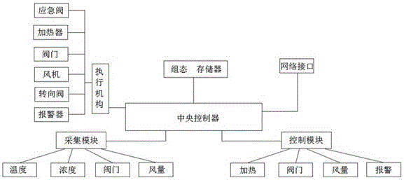
[0025] Embodiment 1: as figure 1 with 2 A control system for an organic waste gas catalytic burner is shown, and the control system includes a central controller, a configuration memory, an acquisition module, a control module and an actuator, and the configuration memory, the acquisition module, the control module and the actuator are all Connected to the central controller, the acquisition module includes temperature, concentration, valve and air volume acquisition modules, the control module includes heating, valves, air volume and alarm modules, and the actuator includes catalytic chambers, reversing valves , fans, intake valves, emergency valves and alarms;

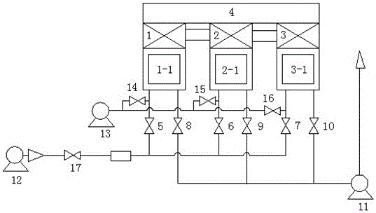
[0026] The control system of the present invention is installed on the organic waste gas catalytic burner, and the organic waste gas catalytic burner includes No. 1 burner, No. 2 burner, No. 3 burner and fan, No. 1, No. 2 and No. 3 The burners communicate with each other, and the intake valve 17 is respectively con...

Embodiment 2

[0027] Embodiment 2: as figure 1 with 2 As shown, No. 1, No. 2 and No. 3 burners of the present invention are all made up of electric heating tube 4, catalytic chamber 1, 2, 3 and regenerator 1-1, 2-1, 3-1, and catalytic chamber 1 . -1, 3-1 flow into the catalytic chambers 1, 2, and 3. During a single operation, the former catalytic chamber 1 has a stable working temperature due to the relatively low-temperature organic waste gas flowing in, but the latter catalytic chamber 2. Since the organic waste gas has been burning, the working temperature at the tail must be high, which can easily cause the activity of the catalyst at the tail to decrease or even deactivate.

Embodiment 3

[0028] Embodiment 3: as figure 1 with 2 As shown, the intake pipe and exhaust pipe of the present invention are all connected to the regenerator 1-1, 2-1, 3-1 of the catalytic chamber, and the regenerator 1-1, 2-1, 3-1 1 and catalytic chambers 1, 2, and 3 are provided with a temperature acquisition module, and the heating module is arranged on the electric heating tube 4; the device as a whole is uniformly controlled by a central controller. It directly affects the purification efficiency of exhaust gas, so it needs to be monitored intensively.


PUM


Abstract

The invention discloses a control system of an organic waste gas catalytic burner and an operation method of the control system. The control system comprises a central controller, a configuration storage, a collection module, a control module and an execution mechanism; the configuration storage, the collection module, the control module and the execution mechanism are all connected to the central controller; the collection module comprises a temperature collection module, a concentration collection module, a valve collection module and a wind amount collection module, the control module comprises a heating module, a valve module, a wind amount module and an alarm module; the execution mechanism comprises a catalysis chamber, a reversing valve, a draught fan, an air inlet valve, an emergency valve and an alarm device; a control system and a waste gas inlet and outlet mode of a traditional organic waste gas catalytic burner are changed, through the circular air inlet and outlet manner of multiple burners, the influence of heat generated by waste gas in the combustion process on a catalyst in the burner can be thoroughly avoided, the generated energy is led into a heat storage chamber of the burner to be preheated through a pipeline in a gas inlet and outlet manner, and the energy utilization rate is high.

Description

technical field [0001] The invention relates to the field of organic waste gas treatment devices, in particular to a control system for an organic waste gas catalytic burner. Background technique [0002] Organic waste gas (Volatile Organic Compounds, referred to as VOC) is one of the main pollution sources of the atmospheric environment. Due to its high toxicity, it is very harmful to human health, especially benzene and polycyclic aromatic hydrocarbons, which violate the human nervous, respiratory, blood and reproductive systems, causing dizziness, dizziness, and nausea in mild cases, and causing Aplastic anemia, leukemia, and cancer are life-threatening, so treatment is urgently needed. [0003] Catalytic combustion is one of the conventional methods for treating organic waste gas, which converts organic waste gas into harmless gas through catalytic reaction and combustion; for conventional catalytic combustion devices on the market, the normal working temperature of the...

Claims


Application Information

Patent Timeline
Patent Type & Authority Applications(China)
IPC IPC(8): F23G7/06F23G7/07
CPCF23G7/063F23G7/07F23G2202/60F23G2202/701F23G2204/20F23G2206/10F23G2207/101F23G2207/112
Inventor 岳仁亮王建平齐丛亮吴傲立
Owner 江苏中科睿赛环境工程有限公司
Why Eureka
Try Eureka