
Control method of refrigerant flow of air conditioner system

An air-conditioning system and refrigerant flow technology, which is applied in the field of air-conditioning, can solve problems affecting the refrigerant flow and the cooling or heating performance of the air-conditioning system, achieving high performance and reducing performance attenuation

Active Publication Date: 2017-04-05
GREE ELECTRIC APPLIANCES INC
View PDF6 Cites 14 Cited by
  • Summary
  • Abstract
  • Description
  • Claims
  • Application Information

AI Technical Summary

Problems solved by technology

The opening of the electronic expansion valve will affect the flow rate of the refrigerant entering the air-jet enthalpy-enhancing compressor, thereby affecting the cooling or heating performance of the air conditioning system

Method used


Image

  • Control method of refrigerant flow of air conditioner system
  • Control method of refrigerant flow of air conditioner system
  • Control method of refrigerant flow of air conditioner system

Examples


Embodiment 1

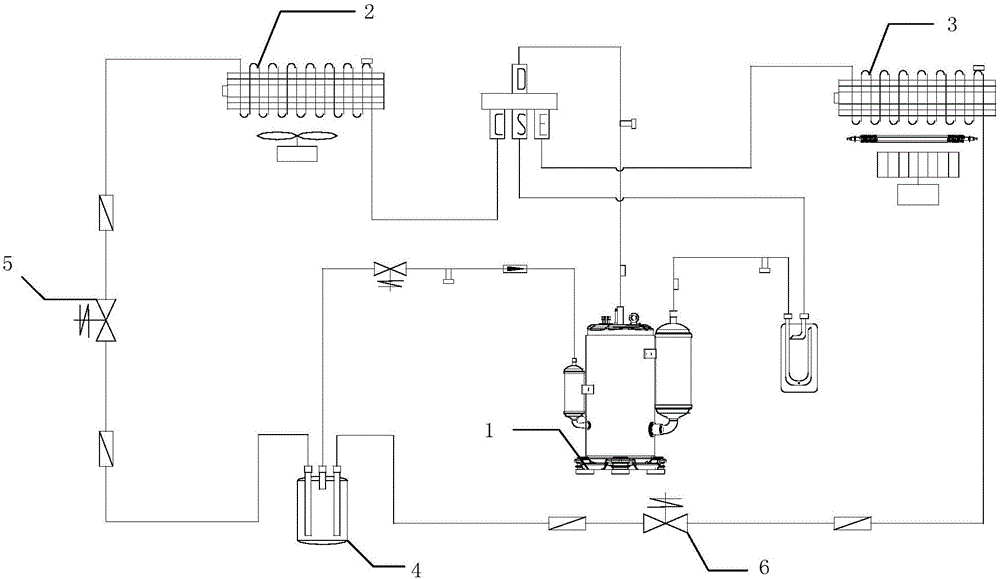
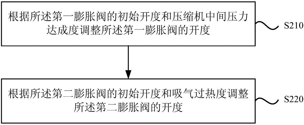
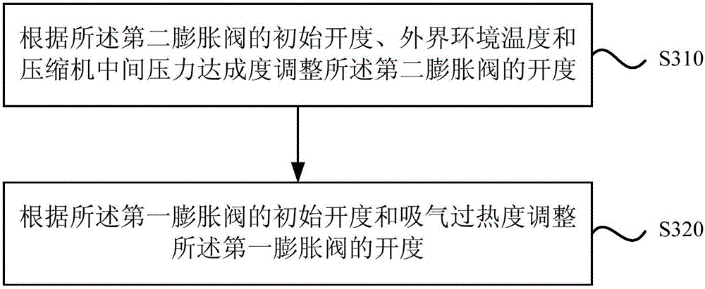
[0046] This embodiment provides a method for controlling refrigerant flow in an air conditioning system. figure 1 A schematic structural diagram of the air-conditioning system in the method for controlling the flow of refrigerant in the air-conditioning system provided by Embodiment 1 of the present invention; figure 2 It is a flow chart of the method for controlling the flow of refrigerant in the cooling mode in the method for controlling the flow of refrigerant in the air-conditioning system provided by Embodiment 1 of the present invention; image 3 It is a flow chart of the method for controlling the flow of refrigerant in the heating mode in the method for controlling the flow of refrigerant in the air-conditioning system provided by Embodiment 1 of the present invention.

[0047] Such as figure 1 As shown, the air conditioning system includes a compressor 1, a condenser 2, an evaporator 3, a flasher 4, a first expansion valve 5 and a second expansion valve 6, and the f...


PUM


Abstract

Disclosed is a control method of the refrigerant flow of an air conditioner system. The method comprises the steps that in the refrigerating mode, the opening degree of a first expansion valve is adjusted according to the initial opening degree of the first expansion valve and the intermediate pressure achievement degree of a compressor, and the opening degree of a second expansion valve is adjusted according to the initial opening degree of the second expansion valve and the air suction superheat degree; and in the heating mode, the opening degree of the second expansion valve is adjusted according to the initial opening degree of the second expansion valve, the external environment temperature and the intermediate pressure achievement degree of the compressor, and the opening degree of the first expansion valve is adjusted according to the initial opening degree of the first expansion valve and the air suction superheat degree. By the adoption of the technical scheme, accurate control over the refrigerant flow is achieved, the air conditioner system can still have relatively high performance under the working conditions of refrigeration at the high temperature and heating at the low temperature, and performance deterioration caused by environmental temperature changes is reduced.

Description

technical field [0001] Embodiments of the present invention relate to the technical field of air conditioning, and in particular, to a method for controlling refrigerant flow in an air conditioning system. Background technique [0002] The gas-injection enthalpy-increasing compressor adopts two-stage throttling intermediate air-injection technology, and uses a flash evaporator for gas-liquid separation to achieve the effect of increasing enthalpy. It mixes and cools air while compressing at medium and low pressure, and then compresses normally at high pressure to increase the displacement of the compressor to achieve the purpose of increasing the heating or cooling capacity. [0003] In some harsh environments, for example, when the ambient temperature is in the range of -40 to 55°C, the compression ratio of the compressor will increase significantly compared with normal working conditions, which will lead to a decrease in the volumetric efficiency of the compressor. Greatl...

Claims


Application Information

Patent Timeline
Patent Type & Authority Applications(China)
IPC IPC(8): F25B41/06F25B49/02F25B41/325
CPCF25B49/02F25B2500/02F25B2600/2513F25B41/31
Inventor 伍健斌卢祥江王严杰
Owner GREE ELECTRIC APPLIANCES INC
Learn More