An offshore sandwich steel pipe pile foundation

A sandwich steel pipe and pile foundation technology, which is applied in infrastructure engineering, coatings, anti-corrosion coatings, etc., can solve problems such as poor compressive capacity and other physical and mechanical indicators, reduce the service life of pipe piles, and require high construction equipment. Natural erosion and instability damage, prolong service life, considerable economic benefits

Active Publication Date: 2019-03-15
LUDONG UNIVERSITY
View PDF4 Cites 0 Cited by
  • Summary
  • Abstract
  • Description
  • Claims
  • Application Information

AI Technical Summary

Problems solved by technology

However, the single pile foundation structure has the following disadvantages: the length of the cantilever above the mud surface is too large, the flexibility is too large and the rigidity is insufficient, the displacement and deformation during the service period are relatively large, and it is difficult to adapt to areas with large water depths; in order to ensure sufficient rigidity and strength, The diameter of a single steel pipe pile is relatively large (generally more than 4 meters), the corresponding wall thickness is also large, and the amount of steel is large; the weight of the entire steel pipe pile is large, and large lifting equipment and large piling hammers are required. It is very high; limited by the capacity of lifting equipment, the maximum diameter of a single steel pipe pile is also limited at present, and it is difficult to use this kind of foundation structure in large wind loads and deep sea areas; The mechanical index is poor, and it does not have the function of shock absorption; at the same time, the material is easily corroded and damaged, which greatly reduces the service life of the pipe pile

Method used


Image

  • An offshore sandwich steel pipe pile foundation

Examples


Embodiment Construction

[0020] In order to make the objects and advantages of the present invention clearer, the present invention will be further described in detail below in conjunction with the examples. It should be understood that the specific embodiments described here are only used to explain the present invention, not to limit the present invention.

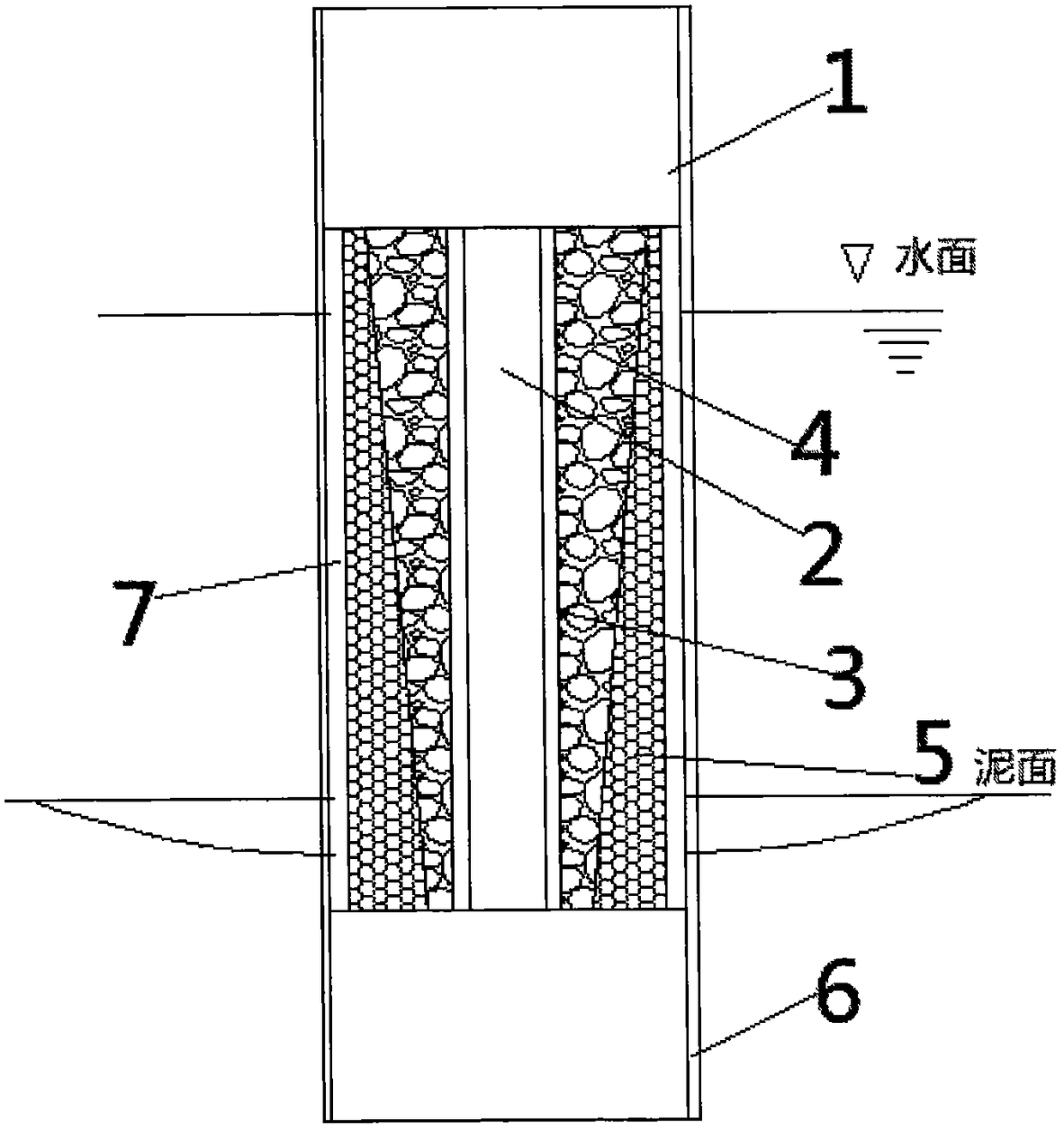
[0021] Such as figure 1 As shown, the embodiment of the present invention provides an offshore sandwich steel pipe pile foundation, including an outer steel pile 1 and an inner steel pipe 2, the inner steel pipe 2 is installed in the outer steel pile 1, and the inner steel pipe 2 is externally connected with a concrete reinforcement layer 4 The concrete reinforcement layer 4 is a hollow circular platform structure, and the diameter of the hollow circular platform decreases sequentially from top to bottom, the concrete reinforcement layer 4 is provided with a bamboo winding layer 5, and the concrete reinforcement layer 4 is provided with three T...


PUM


Abstract

The invention discloses an offshore sandwich steel pipe pile foundation. The offshore sandwich steel pipe pile foundation comprises an outer steel pile and an inner steel pipe. The inner steel pipe is installed in the outer steel pile, a concrete strengthening is connected outside the inner steel pipe in a sleeving mode, the concrete strengthening is of a structure of a hollow circular truncated cone, the diameters of the hollow circular truncated cone dwindle from top to bottom in sequence, a bamboo wrapping layer is arranged outside the concrete strengthening layer, a 37 lime earth layer is arranged between the concrete strengthening layer and the outer wall of the inner steel pipe, an annular space is formed between the outer wall of the bamboo wrapping layer and the outer steel pile, reinforced concrete is poured in the annular space, and an anti-corrosion layer is evenly smeared on the outer wall of the outer steel pile. The concrete strengthening layer of the offshore sandwich steel pipe pile foundation is designed in a big-end-up shape, the center-of-gravity position of the pipe pile foundation is improved, the overall anti-seismic property is strengthened, and natural erosion and buckling failure are avoided through the protection and the tightening-ring action of the bamboo wrapping pipe body; the service life of the sandwich steel pipe pile is prolonged; the cost is reduced, and the economic benefits are considerable; the applicability is improved, and the offshore sandwich steel pipe pile foundation has a wide application prospect in marine engineering.

Description

technical field [0001] The invention relates to the construction field, in particular to an offshore sandwich steel pipe pile foundation. Background technique [0002] Due to the offshore construction, the working conditions are harsh, the construction time is short, the construction is difficult, and it is greatly affected by natural conditions such as weather and sea conditions. [0003] At present, single large-diameter steel pipe piles are one of the basic structure types commonly used in marine engineering, especially offshore wind power projects. Fast and other advantages, suitable for engineering areas with thick soft soil layers. However, the single pile foundation structure has the following disadvantages: the length of the cantilever above the mud surface is too large, the flexibility is too large and the rigidity is insufficient, the displacement and deformation during the service period are relatively large, and it is difficult to adapt to areas with large water...

Claims


Application Information

Patent Timeline
Patent Type & Authority Patents(China)
IPC IPC(8): E02D27/12E02D27/52C09D169/00C09D5/08C09D7/61C09D7/63C09D7/65
CPCC08K2201/011C08L2205/03C08L2205/035C09D5/08C09D7/61C09D7/63C09D7/65C09D169/00E02D27/12E02D27/525C08L33/00C08K13/06C08K3/04C08K2003/2241
Inventor 范庆来张炳磊杨华勋亓良任增乾
Owner LUDONG UNIVERSITY
Why Eureka
Try Eureka