Friction-stir welding device and method thereof

A welding device and friction stir technology, applied in welding equipment, non-electric welding equipment, metal processing equipment, etc., can solve the problems of flash, limited mechanical properties of welds, thinning of welds, etc., to avoid welds. The effect of thinning, eliminating welding flash and improving weld structure

Inactive Publication Date: 2017-04-19
SHANGHAI AEROSPACE EQUIP MFG GENERAL FACTORY
View PDF5 Cites 14 Cited by
  • Summary
  • Abstract
  • Description
  • Claims
  • Application Information

AI Technical Summary

Problems solved by technology

[0007] The object of the present invention is to provide a friction stir welding device and its method to solve the problems of weld seam thinning, limited mechanical properties of the weld seam, and flashing of the weld seam during traditional friction stir welding stirring tool welding

Method used


Image

  • Friction-stir welding device and method thereof
  • Friction-stir welding device and method thereof

Examples


Embodiment Construction

[0017] The friction stir welding device and its method proposed by the present invention will be further described in detail below in conjunction with the accompanying drawings and specific embodiments. Advantages and features of the present invention will be apparent from the following description and claims. It should be noted that the drawings are all in a very simplified form and use imprecise ratios, which are only used to facilitate and clearly assist the purpose of illustrating the embodiments of the present invention.
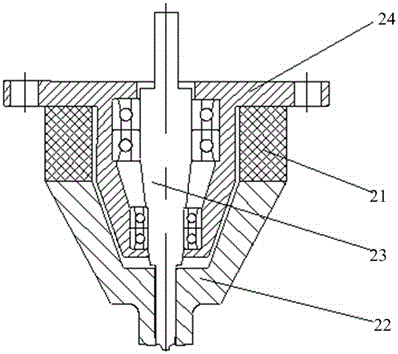
[0018] The core idea of ​​the present invention is that the friction stir welding device provided by the present invention has a simple structure, and the ultrasonic generator, the static luffing shoulder and the stirring pin are integrated through the provided mounting seat, and installed in the friction stir welding device on the head spindle. In the friction stir welding method for workpieces provided by the present invention, the non-rotating stati...


PUM


Abstract

The invention provides a friction-stir welding device. The friction-stir welding device comprises an ultrasonic generator, a variable-amplitude static shaft shoulder, a stirring needle and a mounting base, wherein the ultrasonic generator is in a hollow cylinder shape; the variable-amplitude static shaft shoulder is provided with a mounting opening in one end and coaxially and rigidly connected with the ultrasonic generator; the stirring needle, the ultrasonic generator and the variable-amplitude static shaft shoulder are coaxially mounted, and the non-operating end of the stirring needle is connected with a machine head spindle of the friction-stir welding device; and the mounting base is rigidly fixed to the ultrasonic generator. The invention further provides a method for conducting friction-stir welding on a workpiece through the friction-stir welding device. According to the method for conducting friction-stir welding on the workpiece through the friction-stir welding device, thinning of a weld joint can be effectively avoided through the non-rotational variable-amplitude static shaft shoulder; through high-frequency vibration of the variable-amplitude static shaft shoulder, welding flanges can be completely eliminated; and power ultrasounds are input into weld joint metal through the variable-amplitude static shaft shoulder, the structure of the weld joint can be optimized, and the mechanical performance of the weld joint is improved.

Description

technical field [0001] The invention relates to the technical field of friction stir welding, in particular to a friction stir welding device and method thereof. Background technique [0002] As a solid-phase joining method based on micro-forging, friction stir welding has achieved great success in welding aluminum alloys. figure 1 It is a schematic diagram of the traditional friction stir welding structure. refer to figure 1 , friction stir welding includes a stirring pin 11 and a shaft shoulder 12. During the welding process of friction stir welding, the heat generated by the friction between the high-speed rotating stirring pin 11 and the workpiece is used to locally plasticize the material to be welded. When the stirring pin 11 moves along the welding interface When moving, the plasticized material moves from the front of the stirring needle 11 to the rear under the rotating friction of the stirring needle 11, and forms a dense solid-phase weld under the extrusion of...

Claims


Application Information

Patent Timeline
Patent Type & Authority Applications(China)
IPC IPC(8): B23K20/12B23K20/26
CPCB23K20/12B23K20/1205B23K20/26
Inventor 马子奇沈浩然程怡高嘉爽张靖张聃
Owner SHANGHAI AEROSPACE EQUIP MFG GENERAL FACTORY
Why Eureka
Try Eureka