Concrete pump with lifting type hopper fence

A concrete pump, lift-type technology, applied in the direction of pumps, mixing operation control, clay preparation equipment, etc., can solve the problems of low vibration frequency, low efficiency, and increased maintenance costs of concrete pumps, so as to facilitate replacement and reduce production costs Effect

Inactive Publication Date: 2017-04-19
重庆华耀混凝土有限公司
View PDF6 Cites 0 Cited by
  • Summary
  • Abstract
  • Description
  • Claims
  • Application Information

AI Technical Summary

Problems solved by technology

This fence vibration method improves work efficiency and reduces potential safety hazards, but due to the need to add additional vibration sources and some additional accessories to the concrete pump, the cost of the concrete pump increases, which is not conducive to market promotion; and the concrete pump The working environment is harsh, and the newly added vibration source increases the failure points of the equipment to a certain extent, and its reliability is reduced; in addition, the space above the hopper fence is limited, which brings difficulties to the design of the concrete pump; Inconvenient maintenance, which in turn increases the maintenance cost of the concrete pump
Therefore, many of the above-mentioned shortcomings have led to domestic concrete pump manufacturers not using this mechanism, and still using the original manual method of removing concrete, which is time-consuming, laborious, and inefficient.
[0006] The concrete pump with the patent No. ZL201010127030.0 drives the fence to vibrate through the cam. However, this vibration is rigid and has a very large impact on the concrete pump, hopper, and fence, which will greatly reduce the service life of the concrete pump, hopper, and fence. Moreover, the frequency of this vibration is low, and the problem of concrete accumulation is still not completely solved

Method used


Image

  • Concrete pump with lifting type hopper fence
  • Concrete pump with lifting type hopper fence
  • Concrete pump with lifting type hopper fence

Examples


Embodiment Construction

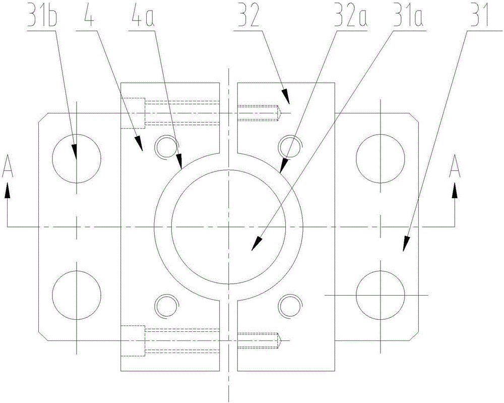
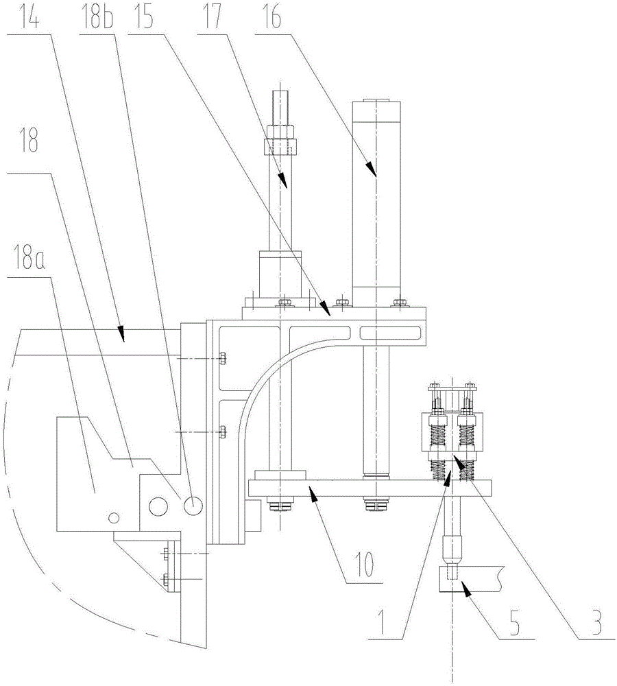
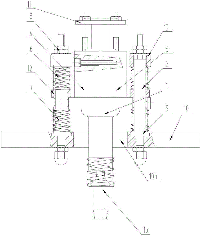
[0028] see Figure 1 to Figure 5, is a concrete pump with a lifting hopper fence, including a concrete mixing device, a hopper and a fence located in the hopper, and a frame 14, and a mounting frame 15 is fixed on one side of the frame 14, and the installation Fix the lifting drive device 16 on the frame 15, the lifting drive device 16 can adopt a cylinder or an oil cylinder, the lifting rod of the lifting driving device 16 extends downwards, a mounting plate 10 is fixed at the lower end of the lifting rod, and the axis line of the lifting rod is perpendicular to the mounting plate 10. A guide column 17 is fixed on the installation plate 10, the upper end of the guide column 17 extends upwards and slides with the installation frame 15, the frame 14 is provided with a limit mechanism 18 of the installation plate 10, the limit The mechanism 18 includes a step limit plate 18a, which is slidably fitted to the chute provided on the frame 14, and at least two steps are provided on t...


PUM


Abstract

The invention discloses a concrete pump with a lifting type hopper fence. The concrete stacking problem is thoroughly solved. The concrete pump comprises a concrete stirring device, a hopper, a fence and a machine frame. An installation frame is fixed to one side of the machine frame. A lifting driving device is fixed to the installation frame. An installation plate is fixed to the lower end of a lifting rod of the lifting driving device. A vibration device is fixed to the installation plate. The vibration device comprises a pneumatic vibrator and a vibrator clamping device. The vibrator clamping device is provided with multiple guide rod through holes. Clamping device guide rods are arranged in the guide rod through holes correspondingly in a sliding fit mode. The upper extending end and the lower extending end of each clamping device guide rod are sleeved with compression springs correspondingly. The lower end of each clamping device guide rod is fixedly connected with the installation plate.

Description

technical field [0001] The invention relates to the field of concrete machinery, in particular to a concrete pump with a lifting hopper fence. Background technique [0002] Concrete pump is a kind of high-efficiency concrete conveying machinery, which is widely used in high-rise buildings, coal mines, mines, tunnels, railways, highways, bridges, ports, water conservancy, electric power, national defense projects and other concrete projects. It continuously presses the concrete to the pouring site through the pipeline, and has good maneuverability. [0003] When the concrete pump is pumping concrete, the concrete delivery tanker needs to continuously dump the concrete into the concrete pump hopper. In order to prevent large materials from entering the hopper and to ensure safe operation, a grid structure fence is generally designed on the upper surface of the hopper. The main The function is to prevent the excessive material in the concrete mortar from entering the hopper, a...

Claims


Application Information

Patent Timeline
IPC IPC(8): B28C5/00B28C7/06B28C7/14F04B15/02
CPCB28C5/00B28C7/06B28C7/14F04B15/02
Inventor 曾华
Owner 重庆华耀混凝土有限公司
Why Eureka
Try Eureka