Vehicle brake cooling system

A heat dissipation system and vehicle braking technology, which is applied in the direction of brakes, brake components, vehicle parts, etc., can solve the problems of inconvenient heat dissipation of brakes, and achieve the effects of increasing cleanliness, reducing pollution, and reducing corrosion

Active Publication Date: 2019-04-05
GUANGXI LIUGONG MASCH CO LTD
View PDF5 Cites 0 Cited by
  • Summary
  • Abstract
  • Description
  • Claims
  • Application Information

AI Technical Summary

Problems solved by technology

[0006] The technical problem to be solved by the present invention is to provide a vehicle brake heat dissipation system with automatic circulation heat dissipation and exhaust functions in view of the inconvenient heat dissipation problem of the existing vehicle brakes

Method used


Image

  • Vehicle brake cooling system
  • Vehicle brake cooling system
  • Vehicle brake cooling system

Examples


Embodiment Construction

[0026] The specific implementation will be described below in conjunction with the accompanying drawings.

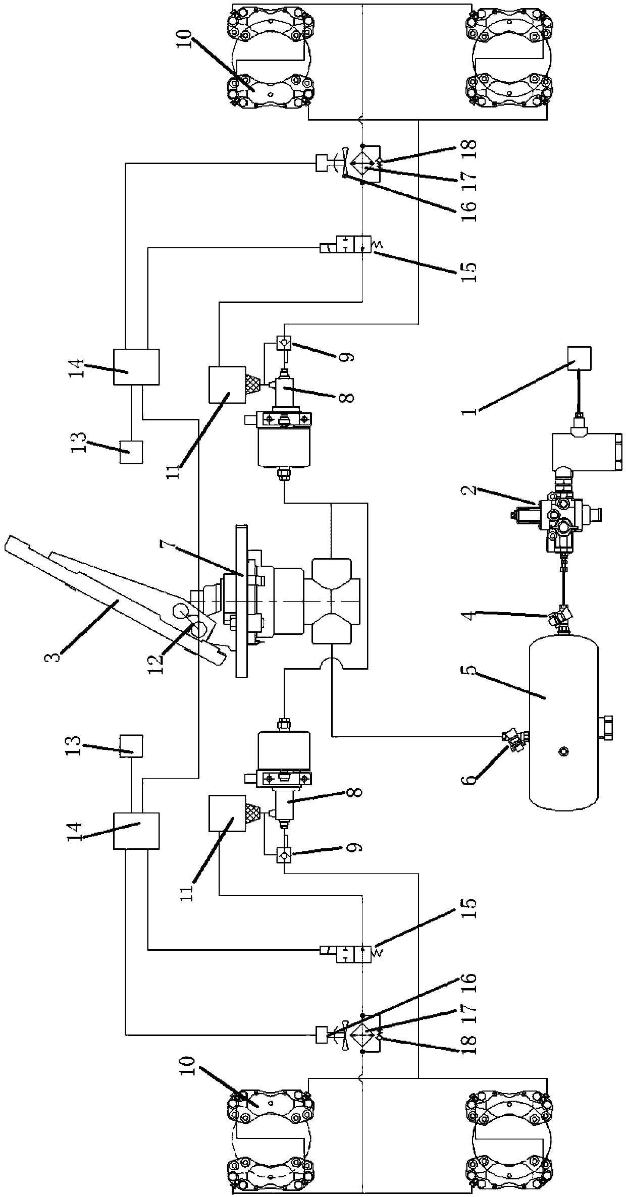
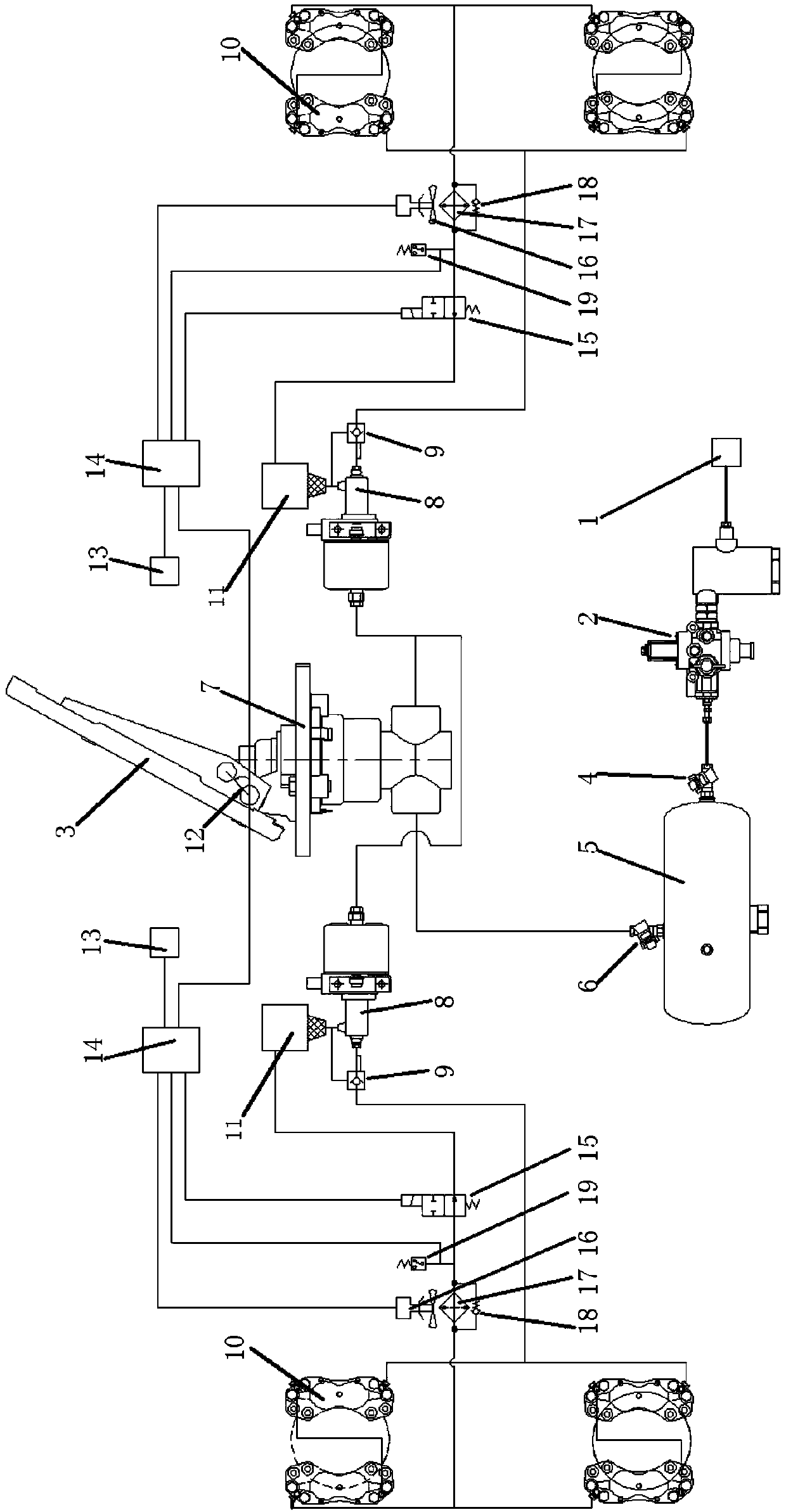
[0027] Embodiment 1 of the vehicle brake cooling system of the present invention is as figure 1 As shown, in this embodiment, the vehicle brake system includes two groups of hydraulic brakes, brake gas supply device, brake pedal 3, brake valve 7, booster 8, hydraulic control check valve 9, brake Hydraulic storage tank 11, angle sensor 12, power supply 13, controller 14, two-position two-way solenoid valve 15, radiator 17, cooling fan 16, second one-way valve 18, angle sensor 12 for detecting the rotation angle of the brake pedal , where the power supply supplies power to electrical components such as the controller.

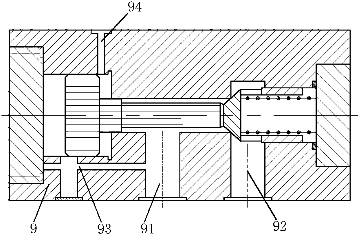
[0028] Such as figure 2 As shown, the hydraulically controlled one-way valve 9 has an inlet 91 and an outlet 92, wherein the inlet 91 is connected to the brake fluid outlet of the booster 8, and the outlet 92 is connected to the brake fluid inlet of the ...


PUM


Abstract

The invention relates to brake systems, and provides a car brake and heat radiation system to solve the problem of inconvenient heat radiation of an existing car hydraulic brake. The car brake and heat radiation system comprises a brake gas supply device, a brake pedal, a brake valve, assistors, hydraulic control one-way valves, brake sets, brake liquid storage boxes, an angle sensor, power sources, controllers, two-position two-way solenoid valves, heat radiation fans, heat radiators, second one-way valves, temperature sensors and pressure sensors. A brake liquid outlet of each assistor is connected with a brake liquid inlet of the corresponding brake set through the corresponding hydraulic control one-way valve, and each heat radiator and the corresponding two-position two-way solenoid valve are sequentially connected between a brake liquid outlet of the corresponding brake set and the corresponding brake liquid storage box in series. A brake liquid supplementary opening of each assistor is connected with the corresponding brake liquid storage box. The control ends of the two-position two-way solenoid valves and the angle sensor are connected with the controllers. In the car brake and heat radiation system, in the process of loosening the brake pedal after brake of every time, after the brake pedal resets to a certain angle, the two-position two-way solenoid valves are connected, part of brake liquid in brakes passes through the heat radiators and the two-position two-way solenoid valves to enter the brake liquid storage boxes, and the heat radiation function of the brakes is achieved.

Description

technical field [0001] The invention relates to a brake system, more specifically, to a vehicle brake system with automatic circulation cooling and exhaust functions. Background technique [0002] At present, loaders have been widely used in various projects and mine construction. After the material is filled, its full load weight is about tens of tons, which puts forward high requirements on the braking performance of the vehicle. Especially in mine construction, many Users always transport materials down the mountain, so when the loader goes down the mountain with a full load, the braking system needs to provide a larger braking torque to meet the safety requirements of the whole machine. [0003] However, in the braking system of traditional loaders used by most existing loaders, the brake valve and the booster are connected through an air pipeline to form an air pressure circuit; the booster and the brake are connected through an oil pipeline to form a brake oil circuit....

Claims


Application Information

Patent Timeline
Patent Type & Authority Patents(China)
IPC IPC(8): B60T5/00B60T13/58B60T17/00
CPCB60T5/00B60T13/581B60T17/002B60T17/004
Inventor 王振兵梁振国谭艳辉陈礼光李泽华王允
Owner GUANGXI LIUGONG MASCH CO LTD
Why Eureka
Try Eureka