Multifunctional AUV based on bionic lateral line

A multi-functional, lateral line technology, applied in two-dimensional position/channel control, vehicle position/route/altitude control, ships and other directions, can solve the problem of underwater pipeline stakeout and detection and positioning, underwater transportation navigation, layout, Problems such as difficult calibration and maintenance, limited scope of action, etc., achieve the effect of novel structure, low cost, and stable support effect

Active Publication Date: 2017-04-19
OCEAN UNIV OF CHINA +1
View PDF7 Cites 26 Cited by
  • Summary
  • Abstract
  • Description
  • Claims
  • Application Information

AI Technical Summary

Problems solved by technology

However, because these systems are difficult in layout, calibration and maintenance, time-consuming and expensive, poor in flexibility, unable to maneuver, and limited in scope of action, they cannot

Method used


Image

  • Multifunctional AUV based on bionic lateral line
  • Multifunctional AUV based on bionic lateral line
  • Multifunctional AUV based on bionic lateral line

Examples


Embodiment 1

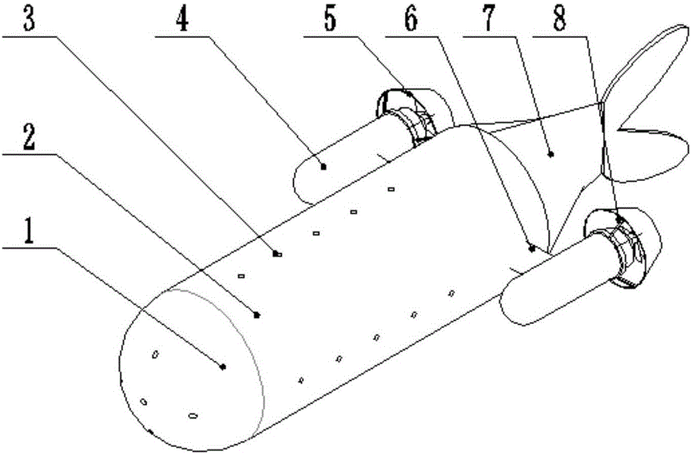
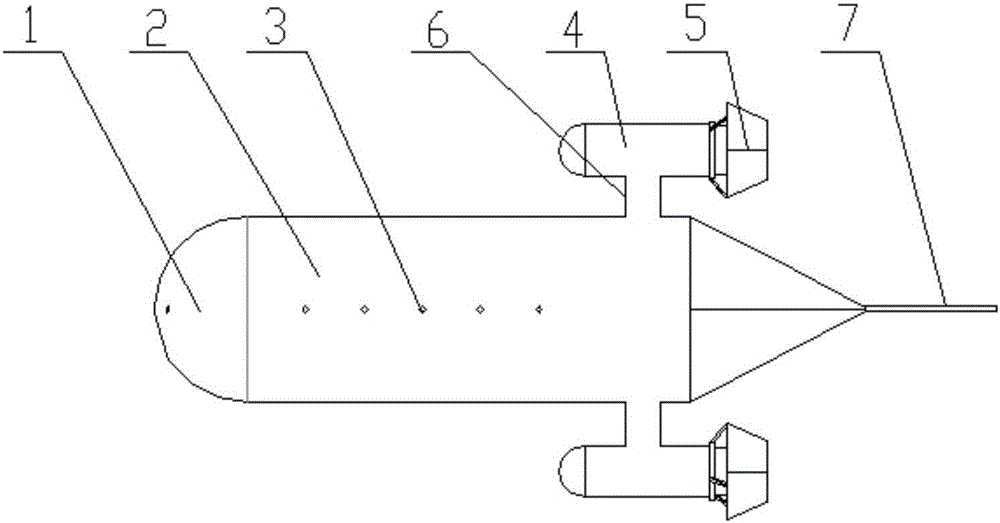
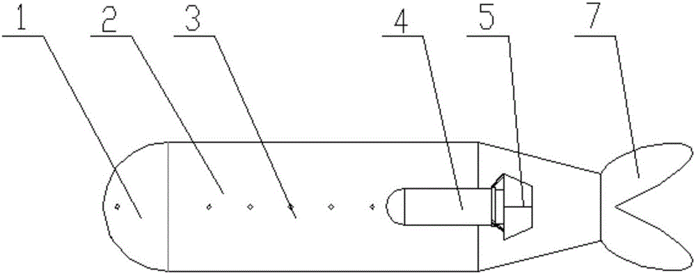
[0028] like Figure 1 to Figure 4 As shown, a multifunctional AUV based on bionic sidelines includes a front head warehouse 1, a main body warehouse 2, a sensor 3, a propeller 4, a shroud 5, a steering gear 6, a tail 7 and blades 8, and the front head warehouse 1, The main body compartment 2 and the tail part 7 are connected head to tail in a streamlined shape, the body compartment is set as a cylindrical compartment, the front compartment 1 is set as a spherical structure, and the front compartment 1 and the main compartment 2 are evenly arranged with bionic side lines and sensor holes are arranged. There are 5 sets in the front head compartment 1, and 20 are evenly arranged on the four sides of the main compartment 2, wherein every 5 sensor holes on the main compartment 2 are set on the same plane, and the distance between adjacent planes is 50mm, and multiple sensors 3 are arranged to form As shown in the linear structure of the bionic side, the sensor 3 is set as a pressur...

Embodiment 2

[0030]The advancing, turning, rising and sinking of the AUV device realizes the movement of six degrees of freedom through the propeller 4 and the steering gear 6 . The sensor 3 is welded on the PCB circuit board and embedded in the carrier shell, leaving a sensing joint in contact with the outside world. It also includes a single-chip microcomputer 9 placed inside the carrier shell, a step-down module, a radio frequency module 12 and a battery 11. The battery 11 passes through the The watertight connector charges the inside and controls the overall internal power supply, and the connection part is watertight through the O-ring. The single-chip microcomputer 9, the radio frequency module 12 and the battery 11 etc. are placed inside the carrier, and the inside is charged through the watertight joint and the overall internal power is controlled. The connection part is made watertight by O-ring.

[0031] The main controller of the single-chip microcomputer 9 of the control syste...


PUM


Abstract

The invention discloses a multifunctional AUV based on a bionic lateral line, sensors are welded on a PCB circuit board and embedded in a carrier casing, a front head cabin, a main body cabin and a tail part are in streamlined head-tail sequential connection, sensor holes showing as the bionic lateral line are evenly distributed on the front head cabin and the main body cabin, the rear ends of both sides of the main body cabin are provided with steering engines, the end parts of the steering engines are connected with propellers, the end parts, far away from the front head cabin, of the propellers are provided with guiding covers, the terminal end of the main body cabin is provided with the tail part, and the tail part is a streamlined fish tail structure. Pressure data is obtained by the sensors which are arranged like the bionic lateral line, and during velocity measurement, a carrier directly faces the flow direction, and can correctly estimate local velocity. The AUV can determine direction and a path of a vibration source by sensing pressure gradients and changes so as to realize underwater positioning or obstacle avoidance. The multifunctional AUV has the advantages of small size and low cost, improves efficiency of identification and intelligentization of underwater equipment, and provides theoretical and data support for flow velocity measurement, underwater positioning and obstacle avoidance.

Description

technical field [0001] The invention belongs to the technical field of underwater robot equipment, and in particular relates to a multifunctional AUV based on a bionic lateral line. Background technique [0002] The lateral line is an important hydrodynamic sensory organ found in fish and amphibians. It can help fish detect and deal with various hydrodynamic situations. The use of the lateral line system for underwater pressure sensing plays an important role in fish behavior. role. The current AUV (autonomous underwater vehicle) underwater obstacle avoidance and positioning mainly uses sonar technology to locate and avoid underwater objects, such as forward-looking sonar, side-scan sonar, and synthetic aperture sonar. Velocity measurement methods mainly use Pitot tubes, hot wire anemometers, laser Doppler current meters and particle image velocimeters, and other methods are evolved based on the basic principles of these methods. Pitot tube speed measurement is based on th...

Claims


Application Information

Patent Timeline
IPC IPC(8): B63C11/52G05D1/00G05D1/02
CPCB63C11/52G05D1/0022G05D1/0206
Inventor 刘贵杰郜述显王安忆王世瑞杨亭亭于敬东
Owner OCEAN UNIV OF CHINA
Why Eureka
Try Eureka