Switching water production method for double-pump water purifier with discharged concentrated water recovery device

A recovery device and water purifier technology, applied in chemical instruments and methods, water/sewage multi-stage treatment, water/sludge/sewage treatment, etc., can solve the problems of unaccustomed users, waste of water, and quality problems of water purification faucets and other problems, to achieve the effect of wide application range, simple machine structure and high utilization rate

Active Publication Date: 2017-04-19
杜也兵
View PDF3 Cites 5 Cited by
  • Summary
  • Abstract
  • Description
  • Claims
  • Application Information

AI Technical Summary

Problems solved by technology

However, the three-pipe gooseneck faucet has brought a new situation: when the spool is closed, due to the water pressure in the machine, it takes 10 to 15 seconds for the water to flow out of the faucet outlet.
In this process, the water droplets flow drop by drop. Users are not used to it. It is generally believed that there is a quality problem in the water purification faucet, and it is difficult to accept this waste of water.
Above-mentioned defect and deficiency have influenced the popularization of water purifier

Method used


Image

  • Switching water production method for double-pump water purifier with discharged concentrated water recovery device
  • Switching water production method for double-pump water purifier with discharged concentrated water recovery device

Examples


Embodiment 1

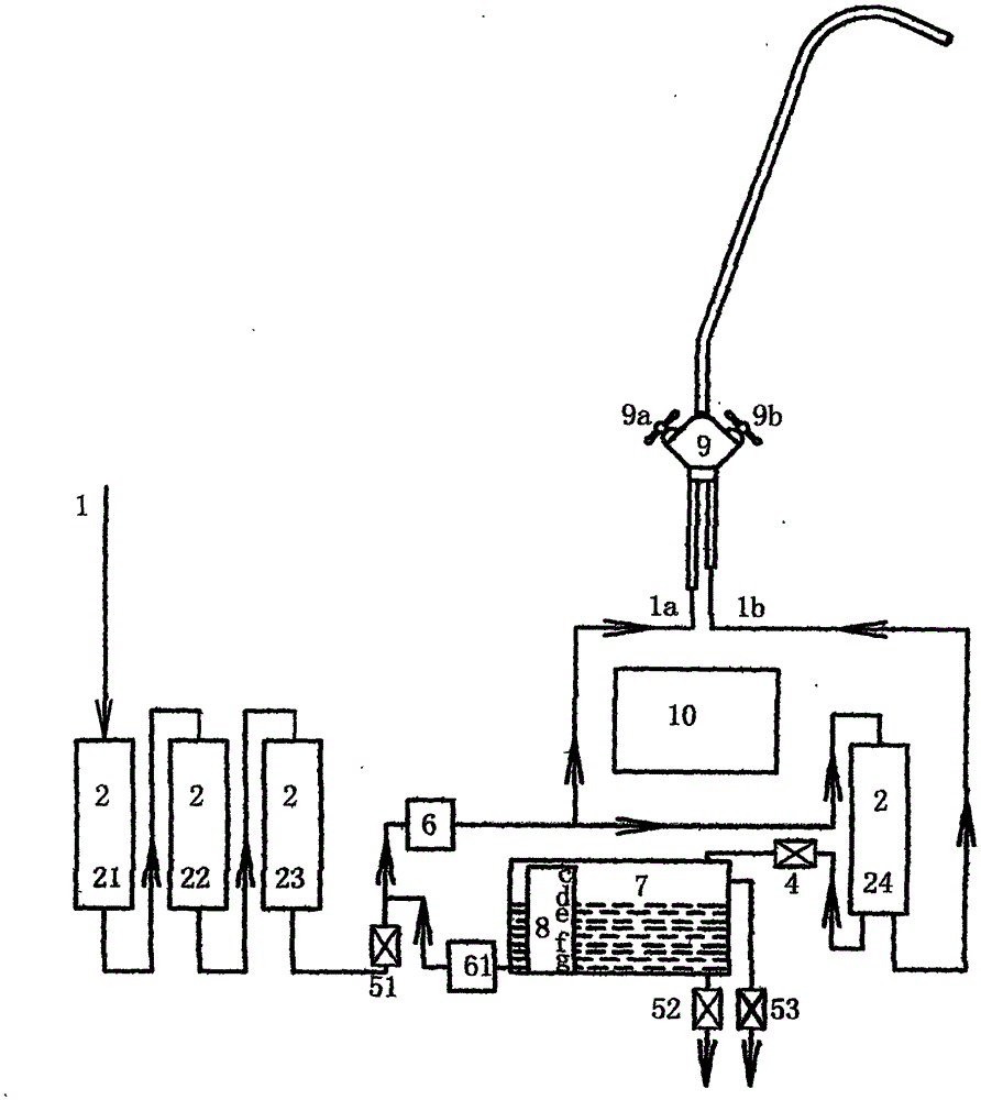
[0021] Example 1. attached figure 1 In the filter channel 1, the pre-filter gall 21, 22, 23 and the fine filter gall 24 provided with the inlet, outlet and concentrated water outlet are connected in series in sequence, and the water outlet of the pre-filter gall 23 is connected to the fine filter gall 24. The booster pump 6 is connected in series between the water ports; the concentrated water port of the fine filter gall 24 is connected to the concentrated water storage device 7 with the water return port through the discharge pipeline of the flow control device 4 (such as the ratio of waste water) provided with the water return port. The return water line of the return water pump 61 is connected with the water inlet line of the booster pump 6, and the connection of the return water line is specifically arranged in the line between the pre-filter gallbladder and the booster pump. The water outlet of the fine filter gall 24 is connected to the pure water interface 1b of the d...

Embodiment 2

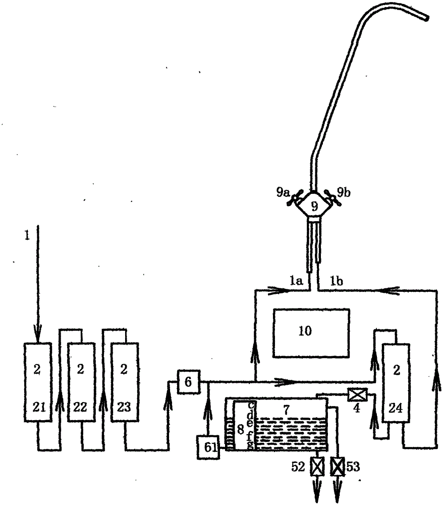
[0029] Example 2. On the basis of Embodiment 1, the connection between the return water pipeline and the pre-filter channel is set in the connection pipeline between the booster pump 6 and the fine filter gallbladder 24, and the water purification pipeline and the water purification valve 9a are connected clean water interface 1a, as attached figure 2 structure shown in. The concentrated water outlet of the fine filter gallbladder 24 is connected to the concentrated water reservoir 7 with a water return port through the discharge pipeline provided with the flow control device 4, and the water return port is connected to the outlet pipe of the booster pump 6 through the return water pipeline with the water return pump 61 road. The water outlet of the fine filter gall 24 is connected to the pure water interface 1b of the double water outlet pressure-bearing faucet.

[0030] Open the water purification valve 9a or the pure water valve 9b of the double water outlet pressure-be...

Embodiment 3

[0041] Example 3. On the basis of Embodiments 1 and 2, the concentrated water storage 7 is set on the base of the machine, and the corresponding return water pump 61 and booster pump 6 are both set on the base.

[0042] As the second mode of Embodiment 3, on the basis of Embodiments 1 and 2, the concentrated water reservoir 7 is separated from the machine base and passed through the water hose and the discharge pipe of the fine filter gall in the filter channel of the machine base Road, and the connection of the pre-filter channel are respectively connected to form a complete circuit of the concentrated water storage tank 7 for storing the concentrated water and the return water pipeline channel. The corresponding return water pump 61 can be located either on the concentrated water storage 7 or on the machine base.


PUM


Abstract

The invention discloses a switching water production method for a double-pump water purifier with a discharged concentrated water recovery device, and relates to the water treatment industry, in particular to filtration of drinking water. All front filter containers and a fine filter container with a water inlet, a water outlet and a concentrated water discharging outlet are sequentially connected in series in a filter channel, and a booster pump controlled by an electric control device is connected between the front filter containers and the fine filter container in series. The concentrated water discharging outlet of the fine filter container communicates with a concentrated water reservoir and is connected with the front filter channel through a return water pipeline. A return water pump in the return water pipeline is further included. The electric control device controls the return water pump to pump discharged concentrated water in the concentrated water reservoir in the water discharging process of the filter channel. A front filter channel control device is used for conveying water together with passing water in the front filter channel or supplying water with the passing water in the front filter channel alternately. When the discharged concentrated water in the concentrated water reservoir falls to a water level lower control limit, the electric control device controls the return water pump to be closed, and the front filter channel control device is turned to control the front filter channel to supply water.

Description

technical field [0001] The invention relates to the water treatment industry, and specifically relates to the deep filtration and purification of drinking water. Background technique [0002] During the use of the water purifier, most of the water consumption is washing water, accounting for about 97%, and drinking water only accounts for about 3%. Higher drinking water. Existing single-outlet water purifiers use the water filtered by all the filters in the filter channel of the machine regardless of whether they use washing water or drinking water, resulting in a waste of a large amount of high-grade water treatment resources and a serious consumption of fine filters with high filtration accuracy. The service life of the filter is also wasted at the same time along with the operation of the nanofiltration membrane filter or the reverse osmosis membrane filter, the concentrated water discharged from the concentrated water outlet in large quantities. In addition, for a wate...

Claims


Application Information

Patent Timeline
Patent Type & Authority Applications(China)
IPC IPC(8): C02F9/02C02F103/04
Inventor 杜也兵冉伊虹
Owner 杜也兵
Why Eureka
Try Eureka