Method for increasing oil recovery rate through self-generation carbon dioxide system after polymer flooding

A carbon dioxide, recovery factor technology, applied in chemical instruments and methods, production fluids, earthwork drilling, etc., to achieve the effects of inhibiting viscous fingering, changing the direction of liquid flow, and expanding sweep efficiency

Inactive Publication Date: 2017-04-19
CHINA UNIV OF PETROLEUM (BEIJING)
View PDF5 Cites 15 Cited by
  • Summary
  • Abstract
  • Description
  • Claims
  • Application Information

AI Technical Summary

Problems solved by technology

However, after polymer flooding, there are few EOR methods that can improve sweep efficiency and oil displacement efficiency.

Method used


Image

  • Method for increasing oil recovery rate through self-generation carbon dioxide system after polymer flooding
  • Method for increasing oil recovery rate through self-generation carbon dioxide system after polymer flooding
  • Method for increasing oil recovery rate through self-generation carbon dioxide system after polymer flooding

Examples


Embodiment 1

[0054] (1) Select the compressed homogeneous artificial core model, the gas permeability is 500mD, the length of the core is 29.55cm, and the cross-sectional area is 4.30*4.35cm 2 .

[0055] (2) Put the core in an oven at 105°C, and dry it until it reaches a constant weight, and record the dry weight as 1024.93g;

[0056] (3) The model was vacuumed for 8 hours, saturated with simulated formation water, the measured pore volume was 135.43mL, and the calculated porosity was 24.50%;

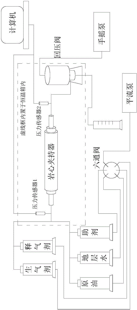
[0057] (4) According to figure 1 Install the displacement experimental equipment and test the tightness;

[0058] (5) Saturated crude oil, oil drives water until the outlet end does not produce water, and the original oil saturation under the state of bound water is calculated to be 64.98%;

[0059] (6) Water flooding with a flow rate of 1.0mL / min, when the water content at the outlet reaches 98%, stop the water flooding;

[0060] (7) Inject a 0.3 PV polymer (polyacrylamide, molecular weight 15 ...

Embodiment 2

[0066] (1) Select the heterogeneous artificial core model in the suppressed layer, the gas permeability is 500 / 2500 / 5000mD, the length of the core is 29.55cm, and the cross-sectional area of ​​the high permeability layer is 4.50*1.47cm 2 , the cross-sectional area of ​​the medium permeation layer is 4.50*1.52cm 2 , the cross-sectional area of ​​the low-permeability layer is 4.50*1.48cm 2 ;

[0067] (2) Put the core in an oven at 105°C, and dry it until constant weight, and record the dry weight as 1053.47g;

[0068] (3) The model was vacuumed for 8 hours, saturated with simulated formation water, the measured pore volume was 162.01mL, and the calculated porosity was 27.25%;

[0069] (4) Install the displacement experimental equipment and test the tightness;

[0070] (5) Saturated crude oil, oil drives water until the outlet end does not produce water, and the original oil saturation under the state of irreducible water is calculated to be 71.36%;

[0071] (6) Water floodin...


PUM


Abstract

The invention provides a method for increasing the oil recovery rate through a self-generation carbon dioxide system after polymer flooding. The method for increasing the oil recovery rate through the self-generation carbon dioxide system after polymer flooding comprises the step that the self-generation carbon dioxide system and spacer fluid are injected into an oil well after polymer flooding. The self-generation carbon dioxide system and the spacer fluid are alternately injected into the oil well multiple times. According to the method for increasing the oil recovery rate through the self-generation carbon dioxide system after polymer flooding, various yield increasing principles are combined, and various technical problems are effectively solved; (1) decompression and injection augmenting effects are achieved, specifically, alkaline blockage relieving and acid blockage relieving of zones near a water injection well are achieved by injecting chemical solutions into the water well, and thus the decompression and injection augmenting effects are achieved; and (2) a heat releasing effect is achieved, so that the viscosity of crude oil is decreased, and the oil displacement efficiency is improved.

Description

technical field [0001] The invention relates to the field of oil and gas field development, in particular, the invention relates to a method for enhancing oil recovery by autogenous carbon dioxide system after polymer flooding. Background technique [0002] Polymer flooding is an important technical means for stabilizing production and improving development results in my country's mature oilfields during high water-cut periods. Polymer flooding can generally increase recovery by 6%-10% on the basis of water flooding. However, after polymer flooding, there are still Nearly half of the original crude oil geological reserves have not been exploited, and the remaining oil is scattered in the formation. Therefore, how to effectively tap the remaining oil and improve oil recovery after polymer flooding is an important guarantee for the sustainable development of oil and gas fields. [0003] At present, the technologies for enhancing oil recovery after polymer flooding include: (1) ...

Claims


Application Information

Patent Timeline
Patent Type & Authority Applications(China)
IPC IPC(8): E21B43/22E21B43/16E21B43/24C09K8/518C09K8/594
CPCC09K8/518C09K8/594E21B43/16E21B43/164E21B43/166E21B43/24
Inventor 侯吉瑞朱道义赵凤兰宋兆杰王建斐吴璇韦琦
Owner CHINA UNIV OF PETROLEUM (BEIJING)
Why Eureka
Try Eureka