A CO shift low-temperature heat utilization method and a CO shift process using the method

A process and heat exchanger technology, which is applied in the field of CO conversion devices, can solve the problems of complex process flow, unreasonable use of the heat of the steam generator sewage, and large fluctuation of influence, so as to optimize the heat exchange network, save operating costs and Occupying area and good operation flexibility

Active Publication Date: 2018-10-19
SINOPEC NINGBO ENG +2
View PDF5 Cites 0 Cited by
  • Summary
  • Abstract
  • Description
  • Claims
  • Application Information

AI Technical Summary

Problems solved by technology

The main disadvantage of this process is that on the one hand, the CO heat exchange network is coupled with the low-temperature methanol washing unit, the process flow is relatively complicated, and the influence between the two is fluctuating; heat of sewage

Method used


Image

  • A CO shift low-temperature heat utilization method and a CO shift process using the method
  • A CO shift low-temperature heat utilization method and a CO shift process using the method

Examples


Embodiment 2

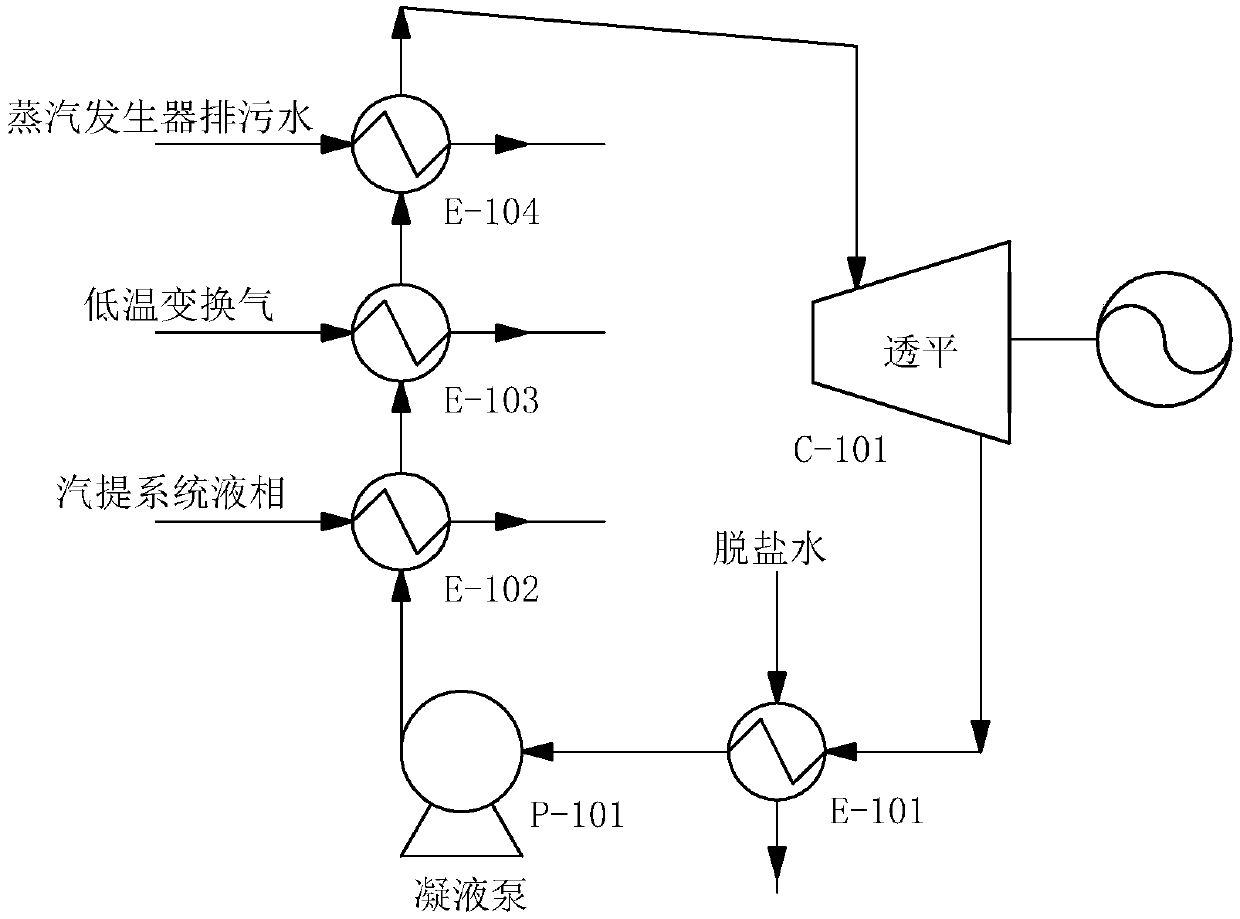
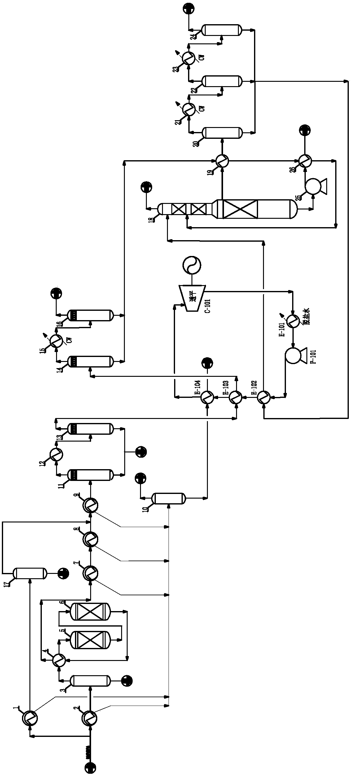
[0035] The 240°C, 6.3MPaG crude synthesis gas from the gasification unit enters the shift unit and is divided into two paths, one for shifted gas and the other for non-shifted gas. The ratio of shifted gas to non-shifted gas is distributed according to the requirements of downstream process equipment.

[0036]The shifted gas is heat-exchanged by No. 1 medium and low pressure steam generator 2, and gas-liquid separated by No. 1 gas-liquid separator 3, and then heated to 250-300°C by the shift furnace inlet heater-medium-pressure steam superheater 4, and sent to Enter the detoxification tank 5 to remove impurities such as dust contained in the converted gas. The detoxified crude synthesis gas enters the shift furnace 6 for CO shift reaction to obtain high-temperature shift gas with a temperature of 420-440°C. The high-temperature shift gas leaving the shift furnace 6 first passes through the shift furnace inlet heater-medium-pressure steam superheater 4 to overheat the 3.0-3.2MP...


PUM


Abstract

The invention involves a CO conversion low-temperature heat utilization method and a CO conversion process using the method. The CO conversion low-temperature heat utilization method is characterized by including the following steps that condensate coming from a desalted water cooler enters a steam stripping condensate heat exchanger after being pressurized through a condensate pump, and exchanges heat with a liquid phase of a steam stripping first-stage separator, a steam stripping second-stage separator and a steam stripping third-stage separator; after being cooled, the liquid phase of the steam stripping first-stage separator, the steam stripping second-stage separator and the steam stripping third-stage separator enters a steam stripping tower; the condensate subjected to heat exchange enters a converted gas heat exchanger and exchanges heat with low-temperature converted gas coming from a conversion 4# gas-liquid separator; the condensate becomes saturated steam; the low-temperature converted gas is cooled to 100-120 DEG C; the saturated steam enters a sewage disposal heat exchanger and exchanges heat with drained sewage coming from a steam generator; after overheating of the saturated steam, the drained sewage is cooled to 120-140 DEG C from 145-160 DEG C; overheated steam is fed to a steam turbine for power generation, and is subjected to isentropic expansion in the steam turbine; and the steam going out of the steam turbine enters the desalted water cooler, and the steam is fed to the condensate pump after exchanging heat with desalted water.

Description

technical field [0001] The invention relates to a CO conversion device, in particular to a CO conversion low-temperature heat utilization method and a CO conversion process using the method. Background technique [0002] The low-temperature heat (160°C-60°C) in the existing industrialized CO conversion process has not been reasonably and effectively integrated and matched, and most of the low-temperature heat is directly cooled by circulating water or air coolers to meet the requirements of downstream process operating parameters . With the expansion of the scale of the device, meeting the requirements of process operation requires larger specifications of the water cooler or air cooler, and consumes a large amount of circulating water or electric energy, resulting in disadvantages such as high operating costs, floor space and energy consumption of the device. [0003] CN103420757 discloses "A Waste Heat Recovery Method for CO Transformation". After the transformed gas pass...

Claims


Application Information

Patent Timeline
Patent Type & Authority Patents(China)
IPC IPC(8): F01K27/02F01D15/10F22B1/16
CPCF01D15/10F01K27/02F22B1/16
Inventor 刘俊刘芹陈国平庞睿冯亮杰余勤锋魏东张臣
Owner SINOPEC NINGBO ENG
Why Eureka
Try Eureka