
General power generation device using seawater tidal energy

A power generation device and tidal energy technology, which is applied in the field of general power generation devices, can solve problems such as large consumption, and achieve the effect of increasing power generation efficiency and water energy utilization

Inactive Publication Date: 2017-04-19
钟群明
View PDF5 Cites 2 Cited by
  • Summary
  • Abstract
  • Description
  • Claims
  • Application Information

AI Technical Summary

Problems solved by technology

[0002] At present, most of the existing power generation devices use thermal power to generate electricity, and such power generation devices need to consume a large amount of fuel such as oil or coal.

Method used


Image

  • General power generation device using seawater tidal energy
  • General power generation device using seawater tidal energy
  • General power generation device using seawater tidal energy

Examples


Embodiment

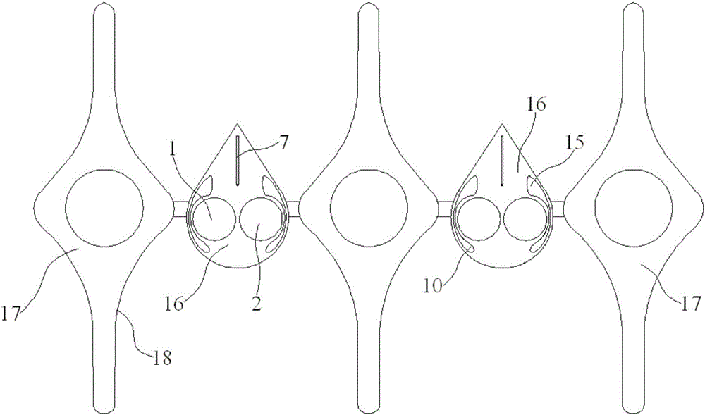
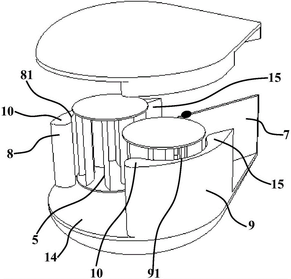
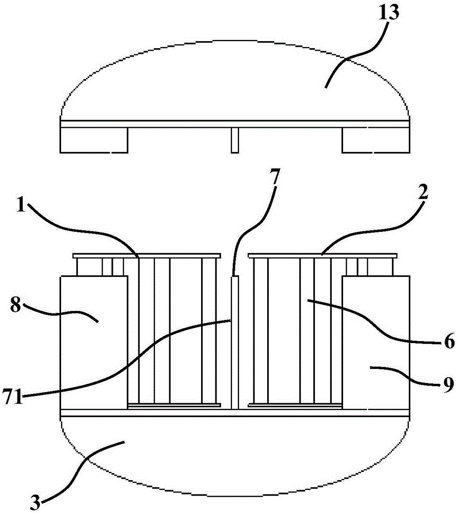
[0023] Embodiment: a kind of general power generation device utilizing seawater tidal energy, as attached Figure 1~5 As shown, it includes: at least 2 power generation modules 16 and at least 3 drainage brackets 17, the at least 3 drainage brackets 17 are arranged at intervals along the width direction, and the power generation modules are installed between adjacent drainage brackets; The module further includes: a left main shaft 1, a right main shaft 2, a base 3 and a generator 4, the base 3 is composed of a circular support 31 at the front and a conical support 32 connected to it and located at the rear, The left main shaft 1 and the right main shaft 2 are rotatably mounted on the left and right sides of the circular support 31 of the base 3. The left main shaft 1 has several left blades 5 distributed along its circumference. The right main shaft 2 Several right blades 6 are distributed along its circumference, and the front end of a tail rudder piece 7 is movably installe...


PUM


Abstract

The invention discloses a vertical water current generator for tides. A base consists of a circular bracket positioned at the front part, and a conical bracket connected with the circular bracket and positioned at the back part; a left main shaft and a right main shaft are rotationally mounted on the left and right sides of the circular bracket of the base; multiple left blades are peripherally distributed on the left main shaft; multiple right blades are peripherally distributed on the right main shaft; the front end of a tail vane blade is movably mounted on the conical bracket through a rotating shaft, so that the tail vane blade can swing left and right around the rotatijng shaft; the rotating shaft for mounting the tail vane blade is positioned on a center extension line between the left main shaft and the right main shaft; a left guide blade and a right guide blade are respectively mounted on the left and right side ends of the circular bracket of the base, and are positioned on the respective opposite outer sides of the left main shaft and the right main shaft; and the front ends of the left guide blade and the right guide blade are movably mounted on two sides of the circular bracket through the rotating shaft. The thrust of water currents to the left blade and the right blade is dynamically adjusted; and the thrust of the water currents to the blades is reinforced to improve the power generation efficiency of the generator and to prevent the damage of the generator under strong water currents.

Description

technical field [0001] The invention relates to hydroelectric power generation, in particular to a general power generation device utilizing seawater tidal energy. Background technique [0002] At present, most of the existing power generation devices use thermal power to generate electricity, and such power generation devices need to consume a large amount of fuels such as oil or coal. However, with the shortage of oil, coal and other fuel resources, the increase in cost, and the pollution of the environment after combustion, people began to increase the development and utilization of environmentally friendly energy, such as solar energy, wind energy, and tidal energy. Power generation devices for generating electricity have become the main subject of energy development nowadays. Therefore, how to design a hydroelectric power generation unit that can make full use of the water level difference generated by the ebb and flow of the ocean and generate mechanical energy throug...

Claims


Application Information

Patent Timeline
Patent Type & Authority Applications(China)
IPC IPC(8): F03B13/26
CPCF03B3/121F03B3/18F03B11/00F03B13/26F03B13/264Y02E10/20Y02E10/30
Inventor 钟群明
Owner 钟群明
Learn More