Proceeding for flushing of pipes at hydraulic systems and a plant for the flushing

A technology of hydraulic system and equipment, applied in the field of pipeline flushing process, can solve the problems of high cost and difficult system, and achieve the effect of compact design, low operation noise and lower operation cost.

Active Publication Date: 2017-04-19
麦基嘉瑞典股份公司
View PDF10 Cites 3 Cited by
  • Summary
  • Abstract
  • Description
  • Claims
  • Application Information

AI Technical Summary

Problems solved by technology

Also, it has been shown how difficult and expensive it actually is to dispose of a contaminated system without completely replacing the components after the fact, if this is at all possible

Method used


Image

  • Proceeding for flushing of pipes at hydraulic systems and a plant for the flushing
  • Proceeding for flushing of pipes at hydraulic systems and a plant for the flushing

Examples


Embodiment Construction

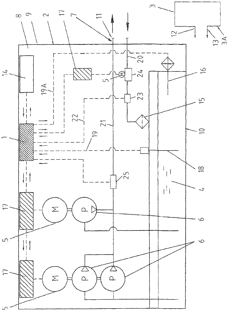
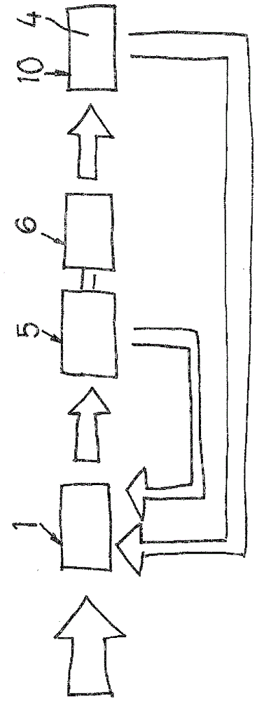
[0050]A process for achieving the so-called flushing of the interior of the pipes of a hydraulic system 3 by supplying a fluid 4 through said hydraulic system 3 as a flow of at least Re 2300 (Renault) according to this The process of the invention is realized in such a way that an automatic cleaning of the hydraulic lines is provided by means of oil 4 or another suitable fluid which is utilized in a so-called closed loop system. Through the pipe size selected in the user interface 14 and by means of the control unit 1, which regulates the motor 5, the pump 6, and the desired degree of purification included in the device 2 utilized, the motor 6 or Feedback of rotational speed of multiple motors 6, turbulent oil flow, and oil temperature.

[0051] The invention according to "closed loop" comprises the steps indicated below.

[0052] I. The operator selects the pipe size in the user interface 14 .

[0053] II. The control unit 1 regulates the motor 5 and the pump 6 through the ...


PUM


Abstract

The invention concerns a proceeding for the pipe flushing of a hydraulic system (3) internally by throughput of said hydraulic system (3) with fluid (4) in a flow of at least Re 2300 Reynolds. According to the invention, motor (5), pump (6) included in utilized plant (2) and the desired purification degree are regulated by a control unit (1) by the feedback of motor speed, oil flow, oil temperature, and contamination degree via particle counter (23). In that connection, there is provided automatic purification of the oil (4) or of another fluid, which is utilized in a so-called closed loop system with corrections automatically made by the control unit (1) after predetermined desired final result of the purification degree before approved result report can be delivered. The invention also concerns a plant (2) for accomplishing a said proceeding.

Description

technical field [0001] The invention relates to a process for pipe flushing of the interior of a hydraulic system by passing a fluid through said hydraulic system, the fluid being a flow of at least Re 2300 Reynolds. Background technique [0002] The flushing of the pipes, i.e. internally cleaning the hydraulic system, takes place according to known procedures related to fluids with turbulent flow of at least Re 3000, in particular in such a way that the degree of contamination of the fluid is measured by inter alia according to ISO 4406:1999 or NAS 1648's particle counter, or by other known similar processes. In piping systems for hydraulic equipment, it is a problem to be able to reliably and efficiently bring all components of a vessel into serviceable condition in a short time and with good results. [0003] Achieving proper flushing has proven to be very problematic worldwide since its introduction into modern hydraulic systems in the 1970s-80s. This manifests itself ...

Claims


Application Information

Patent Timeline
Patent Type & Authority Applications(China)
IPC IPC(8): B08B9/032
CPCB08B9/0325F15B21/005F15B21/041F15B2211/20515F15B2211/6303F15B2211/632F15B2211/6651F15B2211/655F15B2211/615F15B21/087B08B2203/007B08B2203/0223
Inventor T.阿尔伯格K-J.斯特杰纳
Owner 麦基嘉瑞典股份公司
Why Eureka
Try Eureka