Supercharge Your Innovation With Domain-Expert AI Agents!

Device for inspecting junction-type outer joint member of constant velocity universal joint

A universal coupling and inspection device technology, applied in the direction of couplings, elastic couplings, rigid shaft couplings, etc., can solve problems such as the difficult cup-shaped part and the shaft part to be integrally formed, so as to shorten the cycle and ensure quality effect

Active Publication Date: 2017-04-19
NTN CORP
View PDF8 Cites 1 Cited by
  • Summary
  • Abstract
  • Description
  • Claims
  • Application Information

AI Technical Summary

Problems solved by technology

In the long-rod outer coupling member, since the shaft is long, it is difficult to integrally form the cup and the shaft with high precision.

Method used


Image

  • Device for inspecting junction-type outer joint member of constant velocity universal joint
  • Device for inspecting junction-type outer joint member of constant velocity universal joint
  • Device for inspecting junction-type outer joint member of constant velocity universal joint

Examples


Embodiment Construction

[0076] Embodiments of the present invention will be described below based on the drawings.

[0077] First, refer to figure 1 and Figure 2a-2c The first example of the outer coupling member is described, and then, refer to Figure 3-18 A first example of the manufacturing method of the outer joint member will be described.

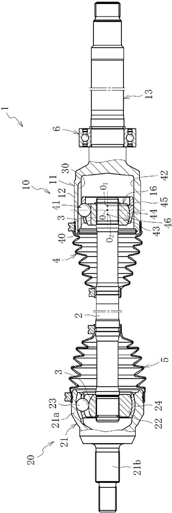
[0078] figure 1 Shows the overall structure of the drive shaft 1. The drive shaft 1 has a sliding constant velocity universal joint 10 , a fixed constant velocity universal joint 20 , and an intermediate shaft 2 connecting both the joints 10 , 20 as main components. The sliding type constant velocity universal joint 10 is arranged on the differential side (the right side in the figure: also called the inner disc side), and the fixed type constant velocity universal joint 20 is arranged on the driving wheel side (the left side in the figure: Also known as the outer disk side).

[0079] The sliding type constant velocity universal joint 10 is a so-ca...


PUM


Abstract

This device for inspecting a junction-type outer joint member of a constant velocity universal joint inspects the outer joint member 11 of a constant velocity universal joint that comprises a bottomed-tube-shaped cup section 12 at the inner periphery of which a track groove is formed in which a torque transmission element rolls, and a shaft section 13 extending in the axial direction from the bottom of the cup section 12, the cup member 12a forming the cup section 12 and the shaft member 13a forming the shaft section 13 being melt-welded together. The inspection device is provided with: a surface inspection unit III that performs an inspection for detecting defects caused by welding and arising at the surface of the outer joint member 11; an inner inspection unit IV for inspecting defects at the inside of the welded section 49; and a storage unit that stores the inspection results of the abovementioned inspections. As a result, it is possible to provide an inspection device that efficiently performs all the inspections in an inline manner with respect to a melt-welded junction-type outer joint member.

Description

technical field [0001] The present invention relates to an outer joint member in which a cup-shaped member and a shaft member of the outer joint member of a constant velocity universal joint are joined by fusion welding (hereinafter referred to as joined type outer joint member). Check the device. Background technique [0002] The constant velocity universal joint that constitutes the power transmission system of automobiles and various industrial machines connects the two shafts on the driving side and the driven side so that torque can be transmitted, and even if the two shafts have an operating angle, they can be equal. quickly transmit rotational torque. Constant velocity universal joints are roughly divided into fixed constant velocity universal joints that allow only angular displacement, and sliding constant velocity universal joints that allow both angular displacement and axial displacement. For example, in the drive shaft of a motor vehicle that transmits power f...

Claims


Application Information

Patent Timeline
Patent Type & Authority Applications(China)
IPC IPC(8): F16D3/20G01N29/275G01N29/28G01N29/48
CPCG01N29/275G01N29/28G01N29/48G01N29/041G01N2291/2626G01N2291/2675F16D3/2055F16D3/227F16D2003/22326F16D1/027F16D2250/0076G01N29/043G01N2291/0289G01N2291/044B21K1/765B23K26/21B23K31/125B23K15/0053G01N2291/2634G01N2291/0234G05B19/4183G01N29/4445F16D3/20G01N21/95G01N2201/06113
Inventor 林宏美香川大辅中川直树今中孝榊原育彦上田时生小林正纯杉山达朗
Owner NTN CORP
Features
  • R&D
  • Intellectual Property
  • Life Sciences
  • Materials
  • Tech Scout
  • Unparalleled Data Quality
  • Higher Quality Content
  • 60% Fewer Hallucinations
Learn More