
Glass rod sintering furnace used for making optical fiber preform

A technology for optical fiber prefabricated rods and glass rods, applied in glass manufacturing equipment, manufacturing tools, etc., can solve the problems of consuming cold furnace downtime and maintenance downtime, damaging glass rods, glass tube workpieces, and affecting production progress, etc., to achieve It is easy to manufacture and maintain, improve the service life, and have the effect of reasonable structure setting

Inactive Publication Date: 2017-04-26
YANGTZE OPTICAL FIBRE & CABLE CO LTD
View PDF5 Cites 1 Cited by
  • Summary
  • Abstract
  • Description
  • Claims
  • Application Information

AI Technical Summary

Problems solved by technology

The melting point of the glass workpiece is about 2000°C. When the furnace is working, the temperature in the furnace is relatively high, and part of the heat generated by the flame naturally rises, making the temperature of the top of the furnace reach a higher temperature. In this case, one or more pieces are often caused. The quartz glass top brick breaks without warning during a working step. Since the two ends of the top brick are supported and installed overhead, the broken top brick will fall due to its own weight and damage the glass rod and glass tube workpiece, which will end the processing and even cause the workpiece to be scrapped.
At the same time, in order to repair the damaged firing furnace, it takes downtime for the cold furnace and maintenance downtime, which seriously affects the production schedule

Method used


Image

  • Glass rod sintering furnace used for making optical fiber preform
  • Glass rod sintering furnace used for making optical fiber preform
  • Glass rod sintering furnace used for making optical fiber preform

Examples


Embodiment Construction

[0016] Embodiments of the present invention will be further described below in conjunction with the accompanying drawings.

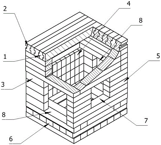
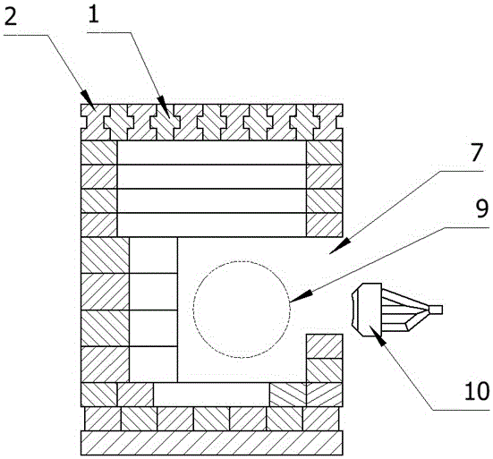
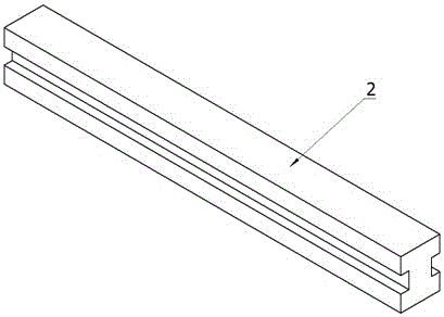
[0017] It includes a box-shaped furnace body. The furnace body includes two sides 3, front and rear sides 5, 4, bottom surface 6 and top surface. The two sides are correspondingly provided with a rod-threading window 8. The rod-threading window is a square, which is convenient for glass preforms. 9, a gas torch window 7 is provided in front of the body of furnace to install the gas torch 10. The two sides, the front, the back and the bottom surface are all spliced ​​by quartz glass strips and quartz glass blocks. The cross section is rectangular; the top surface is constructed by splicing and inlaying quartz glass strip-shaped top bricks with tenons and grooves on the sides, and the strip-shaped top bricks include convex strips with longitudinal tenons symmetrically arranged on both sides. The top brick 1 and the concave strip top brick 2 with longitudin...


PUM


Abstract

The invention relates to a glass rod sintering furnace used for making optical fiber preform. The furnace comprises a box-shaped furnace body, the furnace body comprises two side surfaces, a front surface, a back furnace, a bottom surface and a top surface, the two side surfaces are correspondingly provided with rod traversing windows, the front surface of the furnace body is provided with a combustible gas blast burner window, and the top surface is obtained through splicing and inserting quartz glass strip-shaped bricks laterally respectively provided with tenons and grooves. The furnace can prevent falling of fractured top bricks and avoid damages of processed pieces and interruption of processing, so the working reliability of the sintering furnace is enhanced, and the service life of the sintering furnace is prolonged; mutual embedded connection of the strip-shaped top bricks through the tenons and the grooves forms the seamless quartz glass top surface and improves the heat insulation performance of the sintering furnace; the top surface strip-shaped bricks adopt the grooves or the tenons with a symmetric equal section structure, so the fracture risk of the quartz glass strip-shaped top bricks is reduced, thereby further prolonging the service life of the glass rod sintering furnace; and the furnace has a reasonable structure, and is convenient to make and maintain.

Description

technical field [0001] The invention relates to a glass rod firing furnace for making optical fiber preformed rods, and belongs to the technical field of optical fiber preformed rod manufacturing equipment. Background technique [0002] During the processing of optical fiber preforms, it is often necessary to melt the end faces of two glass rods (tubes) into a butt joint, or melt the ends of the preforms to form a cone or other shapes. Rod firing furnace, through the high-temperature injection combustion of the gas torch in the furnace, the processed end of the glass rod is in a molten state to complete the above work. The glass rod firing furnace has dual functions of combustion and heat preservation. Most of the existing glass rod firing furnaces are constructed of block-shaped quartz materials. A gas blowtorch is installed in the front, and the top surface of the box-shaped firing furnace is composed of strips of quartz glass. top surface. The melting point of the glas...

Claims


Application Information

Patent Timeline
Patent Type & Authority Applications(China)
IPC IPC(8): C03B37/012
CPCC03B37/01205
Inventor 刘涛
Owner YANGTZE OPTICAL FIBRE & CABLE CO LTD
Learn More