Drilling Hydraulic Mining Underground Mining Robot

A technology for robots and mining wells, applied in the field of drilling, can solve the problems of large-scale promotion and application of drilling hydraulic mining technology, insufficient flowback of ore slurry, and difficulty in mining completion, so as to reduce drilling costs, improve production safety, The effect of improving drilling efficiency

Inactive Publication Date: 2017-12-29
CHINA UNIV OF GEOSCIENCES (WUHAN)
View PDF6 Cites 0 Cited by
  • Summary
  • Abstract
  • Description
  • Claims
  • Application Information

AI Technical Summary

Problems solved by technology

[0002] At present, although the drilling hydraulic mining method most commonly used in production can reduce infrastructure investment and improve work safety to a certain extent compared with traditional mining methods, it still has some shortcomings in the actual production process. Predetermined well traces are broken, but cannot be corrected in real time according to the distribution of the underground mine layer to guide it to plan a reasonable path; the surrounding orebodies are only limited to a specific spatial range when the water gun breaks, and for local resources, such as point and local lens It is very difficult to complete the mining of distributed mines; when the ore body is hydraulically broken, the high-speed jet impacts the borehole wall, and the broken and collapsed rock ore body is scattered randomly, which can easily cause accidents such as hole wall collapse, drill sticking, and buried drill, and the ore slurry cannot Sufficient flowback, seriously slowing down mining efficiency, etc.
These problems limit the large-scale popularization and application of drilling hydraulic mining technology for deep solid minerals in production practice.

Method used


Image

  • Drilling Hydraulic Mining Underground Mining Robot
  • Drilling Hydraulic Mining Underground Mining Robot
  • Drilling Hydraulic Mining Underground Mining Robot

Examples


Embodiment Construction

[0024] The principles and features of the present invention will be further described below in conjunction with the accompanying drawings. The examples given are only used to explain the present invention, not to limit the scope of application of the present invention.

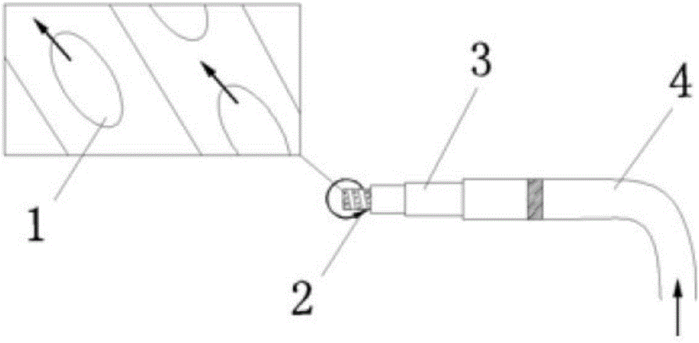
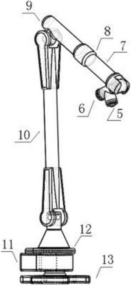
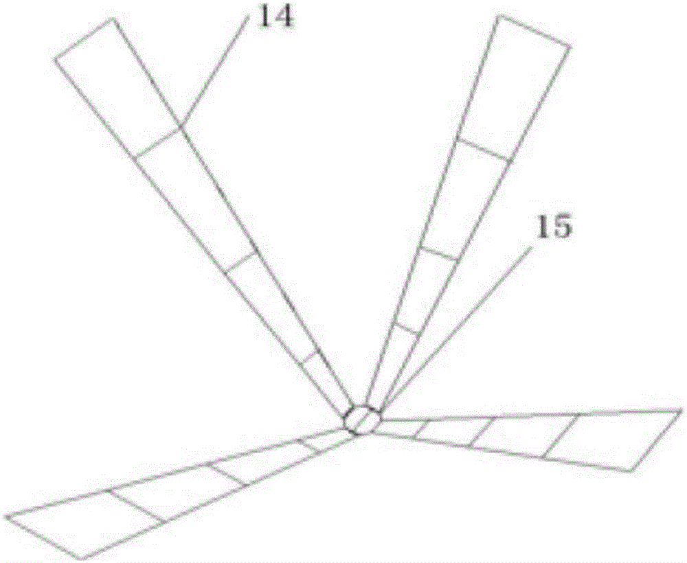
[0025] refer to Figure 1 to Figure 5 As shown, the drilling hydraulic mining underground mining robot of the present invention includes: a spiral hydraulic rotary nozzle 2, a telescopic support 3, a water supply hose 4, an infrared scanning device and a measuring device joint 5, a water supply hose joint 6, Hollow drill string 7, protective cover joint 8, drill pipe inner water pipe joint 9, crank rod 10, integrated electrical control box 11, 360° rotating support 12, mechanical arm base 13, foldable protective blade 14, mechanical arm Connector 15, mobile carrying platform 16, transmission wheel 17, toothed crawler belt 18, transmission shaft base 19, transmission shaft 20, spring shock absorber 21, hydrauli...


PUM


Abstract

The invention discloses a drilling hydraulic mining downhole excavating robot comprising at least a hydraulic giant part, a mechanical force arm, a mechanical arm protective cover, a movable type carrying platform, a robot power transmission device and a robot self-balancing device. A water supply hose joint of the hydraulic giant part is welded to a hollow drill column of the mechanical force arm. A protective cover joint is arranged on the hollow drill column. The mechanical arm protective cover is jointed with the protective cover joint through an inner hexagon screw. A mechanical force arm seat at the bottom of the mechanical force arm is fixed on the movable carrying platform through a bolt, the movable carrying platform is erected on the robot power transmission device, and the robot self-balancing device is erected in the robot power transmission device. The excavating robot can be used for achieve 360-degree all-dimensional intelligentized exploitation in spread space of underground ore bodies, and is suitable for the severe environment such as high temperature and high pressure of a deep hole. Drilling efficiency and drilling quality in the exploration drilling process can be improved obviously, the exploration drilling cost is reduced and production security is increased.

Description

technical field [0001] The invention belongs to the field of drilling, and in particular relates to an underground mining robot for drilling hydraulic mining, which can be widely used in the drilling fields of departments such as geology, coal, and petroleum, and is especially suitable for hydraulic mining of deep solid minerals. Background technique [0002] At present, although the drilling hydraulic mining method most commonly used in production can reduce infrastructure investment and improve work safety to a certain extent compared with traditional mining methods, there are still some shortcomings in the actual production process. Predetermined well traces are broken, but cannot be corrected in real time according to the distribution of the underground mine layer to guide it to plan a reasonable path; the surrounding orebodies are only limited to a specific spatial range when the water gun breaks, and for local resources, such as point and local lens It is difficult to ...

Claims


Application Information

Patent Timeline
Patent Type & Authority Patents(China)
IPC IPC(8): E21C35/00E21C37/12G06T17/05
CPCE21C35/00E21C37/12G06T17/05
Inventor 吴涛陈明张云鹏杨晓伟颜世艳熊远卢春华向龙斌蒋国盛
Owner CHINA UNIV OF GEOSCIENCES (WUHAN)
Why Eureka
Try Eureka