

An Arched Groove Film Cooling Structure for Turbine Blades
A turbine blade and air film cooling technology, applied in the direction of blade support components, engine components, machines/engines, etc., can solve the problems of increased flow resistance, limited jet flow, momentum loss, etc., to increase span-wise coverage and reduce momentum Loss, the effect of reducing flow resistance
- Summary
- Abstract
- Description
- Claims
- Application Information
AI Technical Summary
Problems solved by technology
Method used
Image

Examples
Embodiment 1
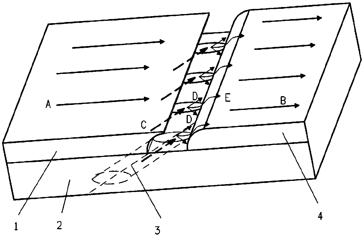
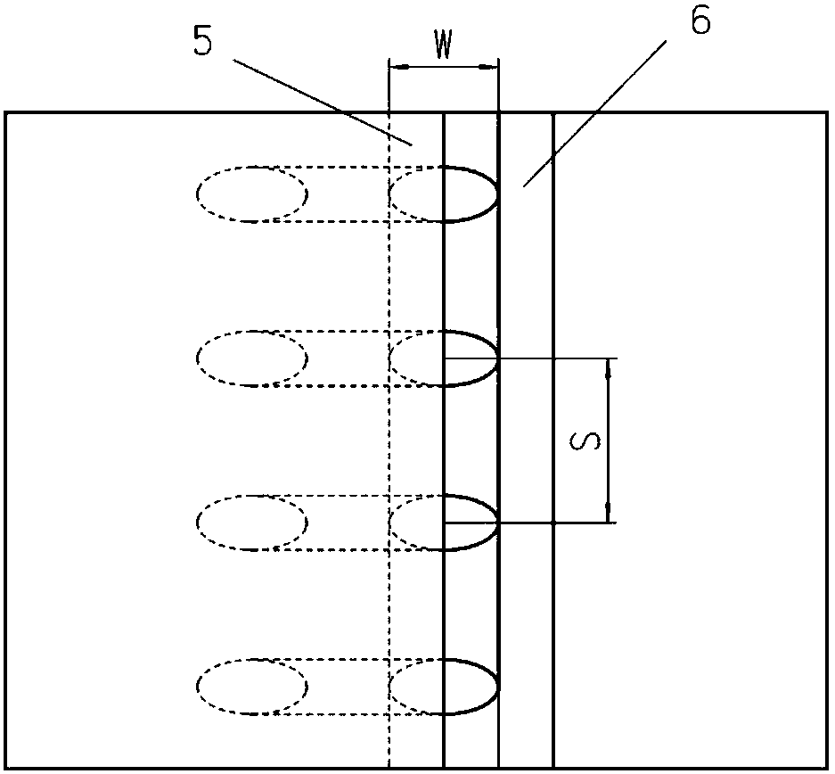
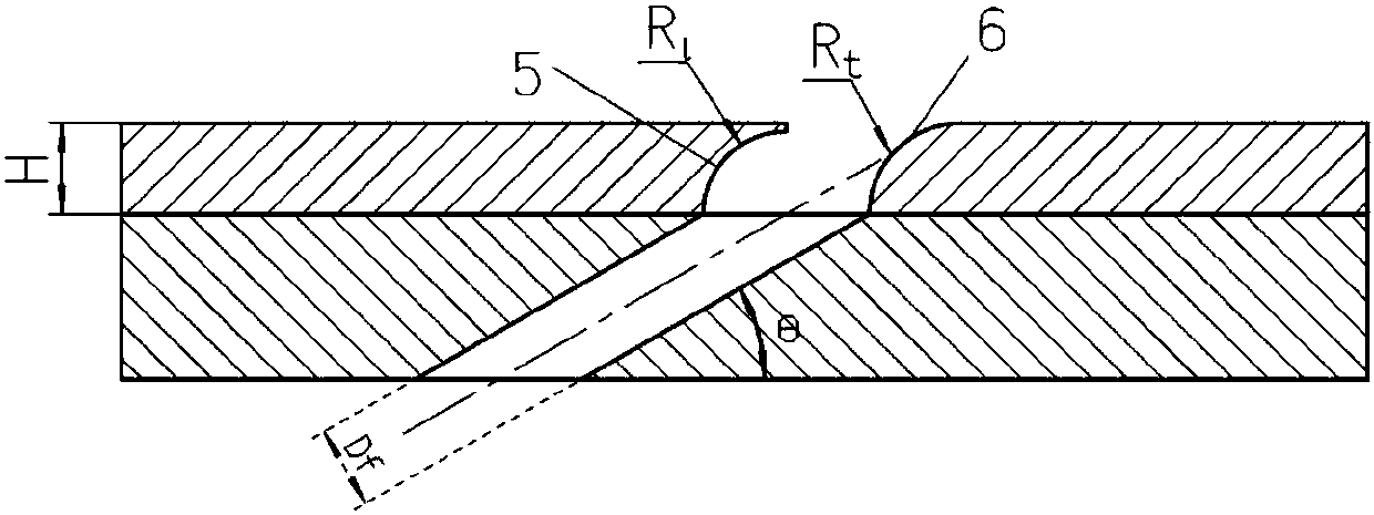
[0029] This embodiment is an arched groove air film cooling structure on the turbine rotor blade. The air film holes 7 with arched grooves are arranged on the pressure surface of the turbine blade, and the air film holes 8 with arched grooves are arranged on the suction surface, and the air is supplied by the inner cooling channel 9; the air film holes located on the air film orifice plate 2 3. The front edge 1 of the arched groove and the rear edge 4 of the groove with rounded corners are arranged at the outlet, and the combination of the front edge 1 of the arched groove and the rear edge 4 of the groove with rounded corners forms the arched groove.
[0030] Among them, the air film hole 3 diameter D f is 0.5mm, and the flow angle θ is 30°. The thickness H of the arched groove leading edge 1 and the groove trailing edge 4 with rounded corners is 1D f , whose value is 0.5mm. The arched groove leading edge 1 is obtained by taking the difference between the bottom of the tra...
Embodiment 2
[0033] This embodiment is an arched groove air film cooling structure applied to a turbine rotor blade. Air film holes 7 with arched grooves are set on the pressure surface of the turbine blades, and air film holes 8 with arched grooves are set on the suction surface of the turbine blades, and the air is supplied by the internal cooling passage 9; on the air film orifice plate 2 The outlet of the air film hole 3 is provided with an arched groove front edge 1 and a groove rear edge 4 with rounded corners, and the combination of the arched groove front edge 1 and the groove rear edge 4 with rounded corners forms an arched groove . Wherein the bottom of the front edge 1 of the arched groove is flush with the front edge of the outlet of the gas film hole 3, and the trailing edge 4 of the groove with rounded corners is flush with the rear edge of the outlet of the gas film hole 3.
[0034] In the structure of this embodiment, the diameter of the gas film hole 3 is D f is 0.5mm, a...
Embodiment 3
[0037] This embodiment is an arched groove air film cooling structure on the turbine rotor blade. The air film holes 7 with arched grooves are arranged on the pressure surface of the turbine blade, and the air film holes 8 with arched grooves are arranged on the suction surface, and the air is supplied by the internal cooling passage 9. It is characterized in that: it is located on the air film orifice plate 2 The air film hole 10 outlet is provided with an arched groove front edge 1 and a groove rear edge 4 with rounded corners, and the combination of the arched groove front edge 1 and the groove rear edge 4 with rounded corners forms an arched groove. Among them, the minimum cross-sectional equivalent diameter D of the gas film hole 10 f is 1mm, and the flow angle θ is 30°. The thickness H of the arched groove leading edge 1 and the groove trailing edge 4 with rounded corners is 1.2D f , its value is 1.2mm. The leading edge 1 of the arched groove is obtained by taking th...
PUM
 Abstract
Description
Claims
Application Information