
Gas outlet end assembly of exhaust system of automobile engine and production technology thereof

A technology for automobile engines and exhaust systems, applied to engine components, machines/engines, exhaust devices, etc., can solve problems such as difficulty in ensuring position tolerances and size requirements, high production costs, and difficulty in ensuring the sealing performance of welding joints, etc.

Inactive Publication Date: 2017-04-26
江苏多为机械工业有限公司
View PDF0 Cites 5 Cited by
  • Summary
  • Abstract
  • Description
  • Claims
  • Application Information

AI Technical Summary

Problems solved by technology

There are many processes and high production costs. Due to the complex structure of the exhaust cone product, it is difficult to ensure the positional tolerance and dimensional requirements between the parts during the combined welding process, and it is difficult to guarantee the sealing performance of the welding parts of the parts.

Method used


Image

  • Gas outlet end assembly of exhaust system of automobile engine and production technology thereof
  • Gas outlet end assembly of exhaust system of automobile engine and production technology thereof
  • Gas outlet end assembly of exhaust system of automobile engine and production technology thereof

Examples


Embodiment 1

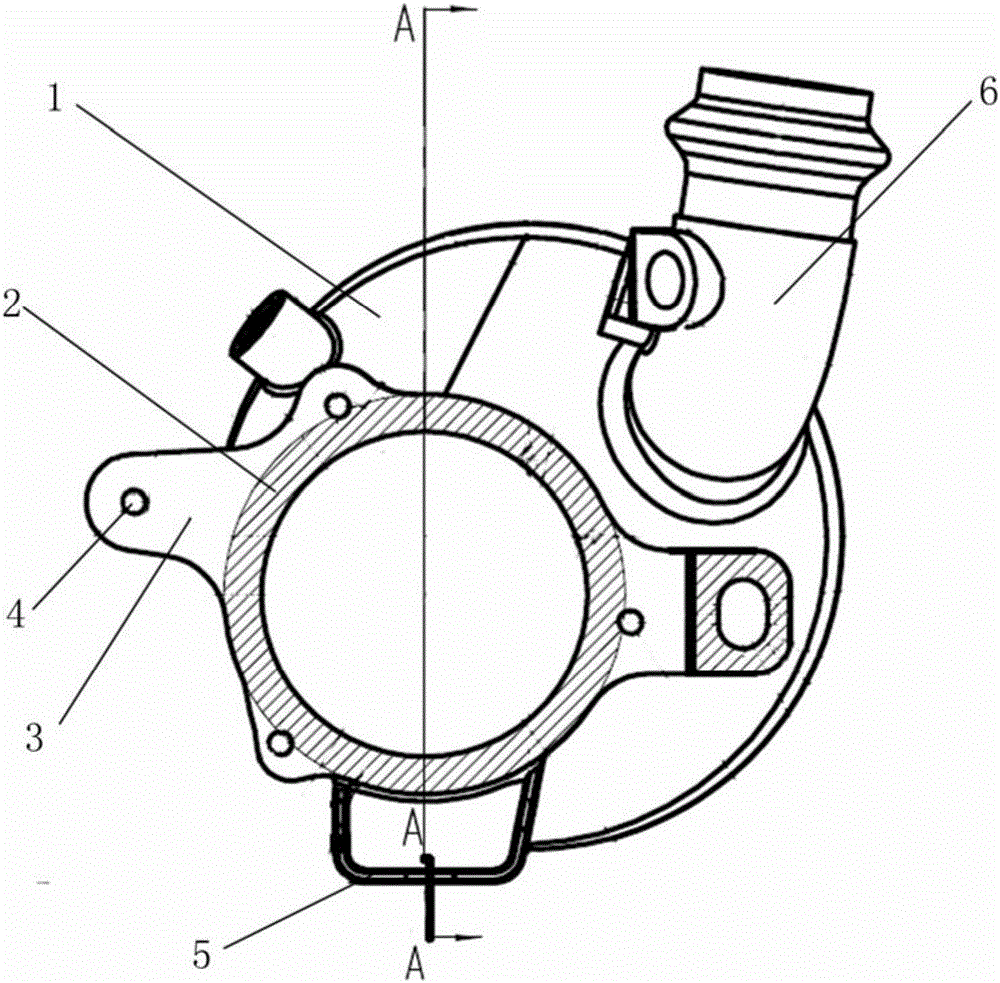
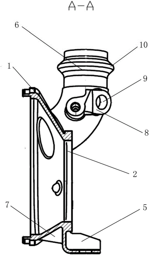
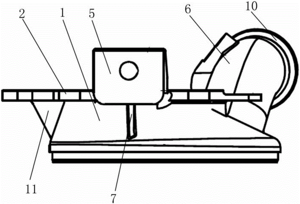
[0085] The automobile engine exhaust cone pipe of the present embodiment, as figure 1 , 2 As shown in and 3, it includes a tapered pipe body 1, an elbow 6 and a connecting flange 2. The tapered pipe body 1 is formed with a cavity from bottom to top, and the elbow 6 and the connecting flange 2 are respectively affixed to the top of the tapered pipe body 1. The elbow 6 and the connecting flange 2 are respectively connected with the cavity, and the tapered pipe body 1, the elbow 6 and the connecting flange 2 are made into one; the elbow 6 is provided with a connecting block 8, and the connecting block 8 is provided with a connecting groove 9. A protruding ring 10 is formed on the end of the elbow 6 away from the tapered pipe body 1 . The connecting flange 2 is fixed vertically upward to the limit block 5 . A first reinforcing rib 7 is formed between the limiting block 5 and the tapered tube body 1 . The connecting end of the connecting flange 2 is horizontally extended outwar...

Embodiment 2

[0131] The automobile engine exhaust cone of the present embodiment comprises a cone body 1, an elbow 6 and a connecting flange 2, the cone body 1 is formed with a cavity from bottom to top, and the elbow 6 and the connecting flange 2 are respectively connected to the cone The top of the body 1 is fixed, the elbow 6 and the connecting flange 2 are respectively connected with the cavity, and the tapered pipe body 1, the elbow 6 and the connecting flange 2 are made as one; the elbow 6 is provided with a connecting block 8, the connecting block 8 is provided with connecting groove 9. A protruding ring 10 is formed on the end of the elbow 6 away from the tapered pipe body 1 . The connecting flange 2 is fixed vertically upward to the limit block 5 . A first reinforcing rib 7 is formed between the limiting block 5 and the tapered tube body 1 . The connecting end of the connecting flange 2 is horizontally extended outwards with bosses 3 , there are four bosses 3 , and through holes...


PUM


Abstract

The invention discloses a gas outlet end assembly of an exhaust system of an automobile engine. The gas outlet end assembly comprises a tapered tube body, an elbow and a connecting flange, wherein the tapered tube body is provided with a cavity from bottom to top; the elbow and the connecting flange are fixedly connected with the top of the tapered tube body; the elbow and the connecting flange communicate with the cavity; and the tapered tube body, the elbow and the connecting flange are manufactured into an integral body. A production technology comprises the steps of (I) smelting raw materials; (II) preparing a wax mold; (III) manufacturing a sand mold of a shell mold; (IV) carrying out dewaxing; (V), roasting the shell mold; (VI) forming the sand mold; (VII) shaving planes of the sand mold and a sand box, and punching air holes in the sand mold; (VIII) carrying out pouring; (IX) turning a casting formed through pouring; and (X) coating the turned casting with a metallic wear-resistant coating. According to the gas outlet end assembly of the exhaust system of the automobile engine, the tapered tube body, the elbow and the connecting flange are manufactured into an integral body, so that relative to traditional assembled exhaust tapered tubes, the tapered tube has the advantages of being higher in structural strength, more stable in working and longer in service life.

Description

technical field [0001] The invention relates to an exhaust end assembly of an automobile engine exhaust system and a production process thereof, belonging to the technical field of auto parts. Background technique [0002] The automobile engine exhaust cone is an important part of the automobile exhaust system. It is made of 304 stainless steel round rods and pipes. The workpiece is the carrier connecting the turbocharger and the three-way catalytic converter. It requires no leakage and high temperature resistance. Requirements, the specific indicators are: [0003] (1) 0.2MPa pressure, no leakage for 1 minute; [0004] (2) High temperature resistance above 750º; designed by the original foreign customer, the exhaust cone is divided into seven parts, and each part is stamped, stretched, bent, mechanically processed, and combined and welded. There are many processes and high production costs. Due to the complex structure of the exhaust cone product, it is difficult to ensur...

Claims


Application Information

Patent Timeline
IPC IPC(8): F01N13/08F01N13/14B22C9/04B22C9/22C22C38/02C22C38/04C22C38/06C22C38/22C22C38/24C22C38/26C22C38/28C22C38/30C22C38/32C22C38/42C22C38/44C22C38/46C22C38/48C22C38/50C22C38/54
CPCF01N13/082B22C9/04B22C9/22C22C38/002C22C38/005C22C38/007C22C38/008C22C38/02C22C38/04C22C38/06C22C38/22C22C38/24C22C38/26C22C38/28C22C38/30C22C38/32C22C38/42C22C38/44C22C38/46C22C38/48C22C38/50C22C38/54F01N13/16F01N13/1844
Inventor 高军陈杰朱铭
Owner 江苏多为机械工业有限公司
Learn More