Turbine wheel for a radial turbine

A turbine impeller, radial flow technology, applied in the field of turbine impeller, to achieve the effect of high torsion resistance

Inactive Publication Date: 2017-04-26
ATLAS COPCO ENERGAS
View PDF0 Cites 17 Cited by
  • Summary
  • Abstract
  • Description
  • Claims
  • Application Information

AI Technical Summary

Problems solved by technology

However, this subsequent fastening is largely disadvantageous due to the high undercut effect and material weakening that occur when joining the cover plate
In addition, an additional mass of the turbine wheel has to be used and additional manufacturing tolerances result

Method used


Image

  • Turbine wheel for a radial turbine
  • Turbine wheel for a radial turbine
  • Turbine wheel for a radial turbine

Examples


Embodiment Construction

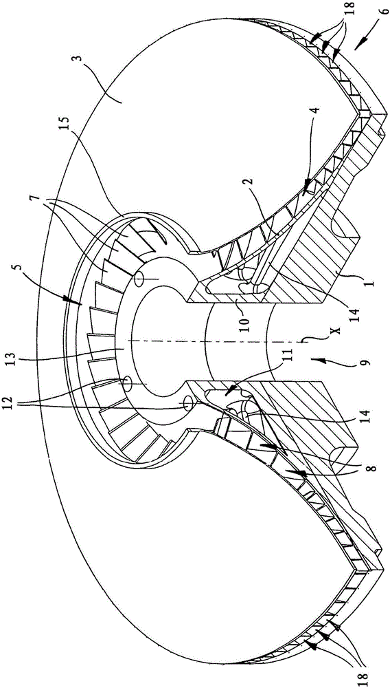
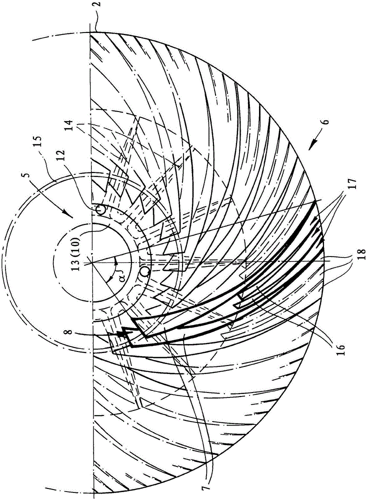
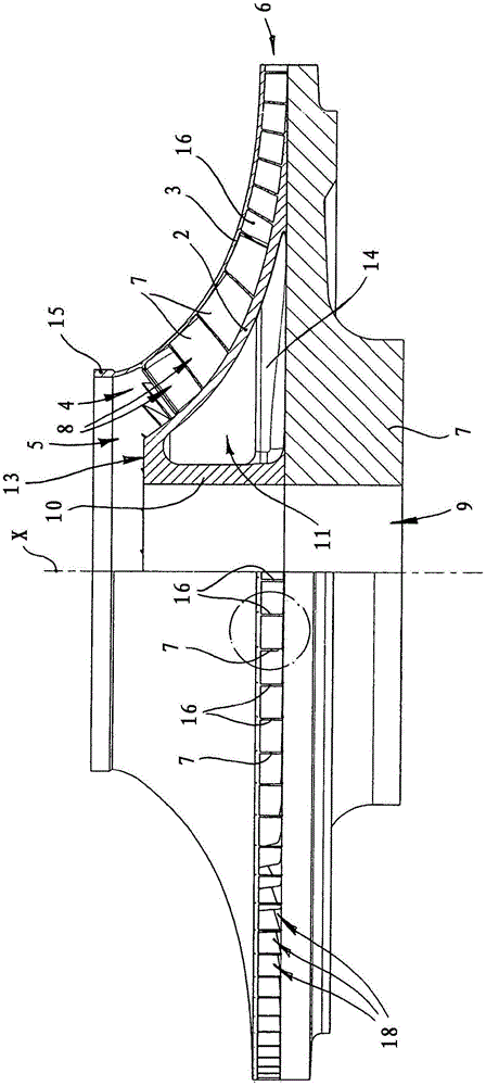
[0030] figure 1 A turbine wheel according to the invention is shown which comprises a base plate which is rotationally symmetrical about an axis of rotation x. For this purpose, a flow space 4 bounded by the hub disk 2 and the cover disk 3 is provided. The flow space connects the axial inner opening 5 with the radial circumferential outer opening 6 of the turbine wheel. It can be seen in a radial section that both the cover disk and the hub disk are formed with a substantially constant thickness in the direction from the inside to the outside. The hub disk 2 has a greater thickness than the cover disk 3 and merges into the base plate 1 in the radially outer region. The flow space 4 is divided into flow channels 8 by turbine blades 7 .

[0031] According to the invention, the hub disk 2 , the turbine blade 7 and the cover plate 3 are integrally formed on the base plate 1 by means of an additive manufacturing method.

[0032]The base plate 1 has a central hub guide passage 9...


PUM


Abstract

The invention relates to a turbine wheel for a radial turbine. A turbine wheel for a radial turbine includes a rotationally symmetrical base plate (1) and a flow chamber (4) delimited by a hub disk (2) and a cover disk (3), wherein the flow chamber connects an axial inner opening (5) to a radial outer opening (6) and is subdivided by turbine blades (7) into flow channels (8). In a method for producing such a turbine wheel, the hub disk (2), the turbine blades (7) and the cover disk (3) are integrally formed on the base plate (1) using additive production methods.

Description

technical field [0001] The invention relates to a turbine wheel for a radial turbine comprising a rotationally symmetrical base plate and a flow space delimited by a cover plate and a hub plate, which connects an axially inner opening to a radially outer The openings are connected and divided into flow channels by the turbine blades. The invention also relates to a method for producing such a turbine wheel. Background technique [0002] Such a closed turbine wheel, a so-called cover disk rotor, has the advantage that the medium guided by the turbine flows through its interior without coming into contact with the outer wall of the turbine. This allows a larger gap width between the turbine wheel and the turbine housing, so that even larger thermal expansions can be compensated without problems and without loss of efficiency. [0003] Turbine wheels are usually produced by machining by cutting. However, restrictions arise here with respect to the producible geometry of the ...

Claims


Application Information

Patent Timeline
Patent Type & Authority Applications(China)
IPC IPC(8): F04D29/28F04D29/22B23P15/00
CPCB23P15/006F04D29/2222F04D29/281F04D29/284F05D2230/234B22F10/28F01D5/043F01D5/14F05D2230/53F05D2210/42B22F5/009B33Y80/00B33Y10/00F01D5/048F01D5/34F05D2230/22Y02P10/25B23K26/342F05D2240/30
Inventor L·施瓦茨
Owner ATLAS COPCO ENERGAS
Why Eureka
Try Eureka