Misplacement correction device for connection plate of hanging rod
A technology of calibrating device and connecting plate, applied in the direction of pipes/pipe joints/fittings, pipe supports, mechanical equipment, etc., can solve the problems of poor matching practicability and lack of matching structural design, and achieve easy operation and good support effect. , high-strength effect
- Summary
- Abstract
- Description
- Claims
- Application Information
AI Technical Summary
Problems solved by technology
Method used
Image
Examples
Embodiment 1
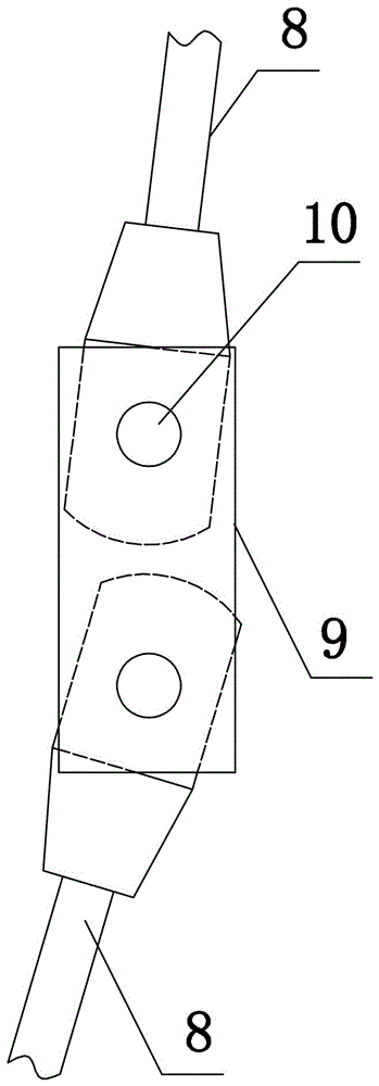
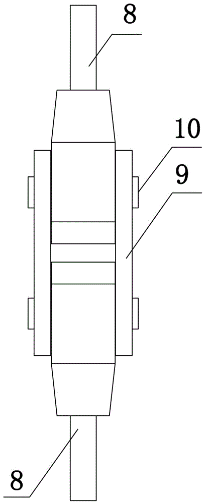
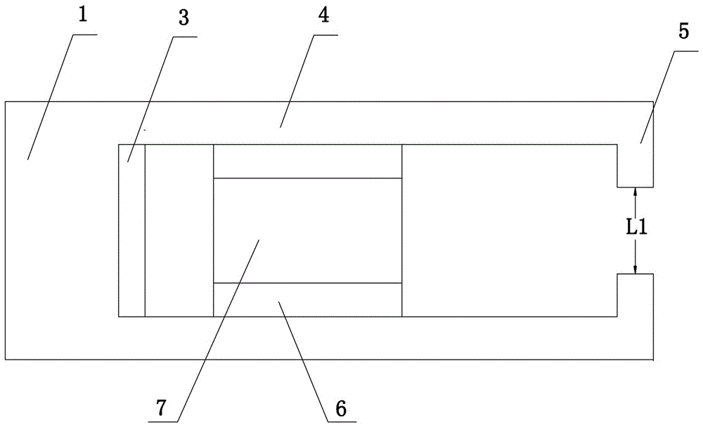
[0032] Such as image 3 and Figure 4 As shown, the present invention discloses a device for correcting the dislocation of the connecting plate of the boom, which includes a bearing plate 1 and a pushing mechanism 2, and the pushing mechanism 2 adopts a hydraulic jack, which is easy to carry, install and use;
[0033] The bearing plate 1 is a cuboid structure, the upper and lower ends of the bearing plate 1 are welded with the reinforcement plate 3, the right end surface of the reinforcement plate 3 is flush with the right end surface of the bearing plate 1, and the right end of the bearing plate 1 is symmetrically arranged with L-shaped rods ;
[0034] The two L-shaped rods are in the shape of an inner button, including a horizontal rod 4 and a vertical rod 5, and the width between the two horizontal rods 4 is L5, and the bearing plate 1, the horizontal rod 4 and the vertical rod 5 are integrally formed , the left end of the transverse bar 4 is connected with the right end ...
Embodiment 2
[0044] The invention discloses a device for correcting the dislocation of a connecting plate of a suspender, which comprises a force bearing plate 1 and a pushing mechanism 2. The pushing mechanism 2 adopts a hydraulic jack, which is convenient for carrying, installation and use;
[0045] The load-bearing plate 1 is a cuboid structure, the upper and lower ends of the load-bearing plate 1 are welded with the reinforcement plate 3, the reinforcement plate 3 is a T-shaped structure, the right end surface of the reinforcement plate 3 is flush with the right end surface of the load-bearing plate 1, and the load-bearing The right end of the plate 1 is symmetrically arranged with L-shaped rods, the two L-shaped rods are in the shape of an inner button and the width between them is L5;
[0046] The L-shaped bar includes a transverse bar 4 and a vertical bar 5. The bearing plate 1, the transverse bar 4 and the vertical bar 5 are integrally formed. The left end of the transverse bar 4 is...
Embodiment 4
[0054] The structure of the present embodiment is basically the same as that of the third embodiment, the difference is: as Figure 8 As shown, the right ends of the two horizontal rods 4 are provided with second threads 16, and the second threaded holes 16 are internally threaded to connect the second bolts 17, and the vertical rods 5 are welded to the inner ends of the second bolts 17. This structural design makes the two The distance between the vertical rods 5 is adjustable, which further improves the practicability of the present invention; the top of the ejector mechanism 2 is detachably connected (threaded or socketed) to the top cover 18, and the value of the diameter R2 of the top cover 18 is connected to two The width between the plates 9, when the structure is designed in use, the dislocation correction process will be completed when the top cover 18 is in contact with the left end surfaces of the two connecting plates 9, and the center line of the boom 8 and the cen...
PUM
 Abstract
Description
Claims
Application Information
 - R&D
- Intellectual Property
- Life Sciences
- Materials
- Tech Scout
- Unparalleled Data Quality
- Higher Quality Content
- 60% Fewer Hallucinations
Browse by: Latest US Patents, China's latest patents, Technical Efficacy Thesaurus, Application Domain, Technology Topic, Popular Technical Reports.
© 2025 PatSnap. All rights reserved.Legal|Privacy policy|Modern Slavery Act Transparency Statement|Sitemap|About US| Contact US: help@patsnap.com


