Heat pump dryer

A technology for dryers and heat pumps, which is applied in the direction of dryers, drying, heat pumps, etc., can solve the problems of high energy consumption, unfavorable energy conservation and environmental protection, and achieve the effect of reducing heat pump power consumption

Pending Publication Date: 2017-04-26
GREE ELECTRIC APPLIANCES INC
View PDF7 Cites 11 Cited by
  • Summary
  • Abstract
  • Description
  • Claims
  • Application Information

AI Technical Summary

Problems solved by technology

[0005] Therefore, the technical problem to be solved by the present invention is to overcome the technical defect of the heat pump dryer in the prior art that consumes a lot of energy, which is not conducive to energy conservation and environmental protection, so as to provide a heat pump dryer that greatly reduces energy consumption and is conducive to energy conservation and environmental protection.

Method used


Image

  • Heat pump dryer
  • Heat pump dryer
  • Heat pump dryer

Examples


Embodiment

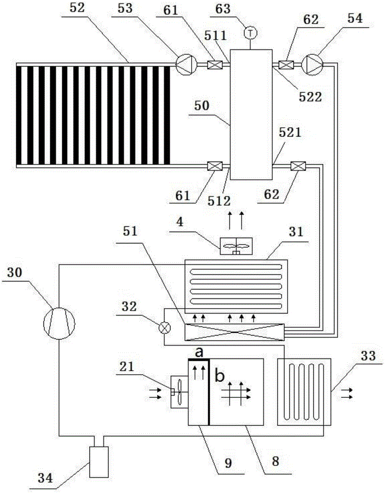
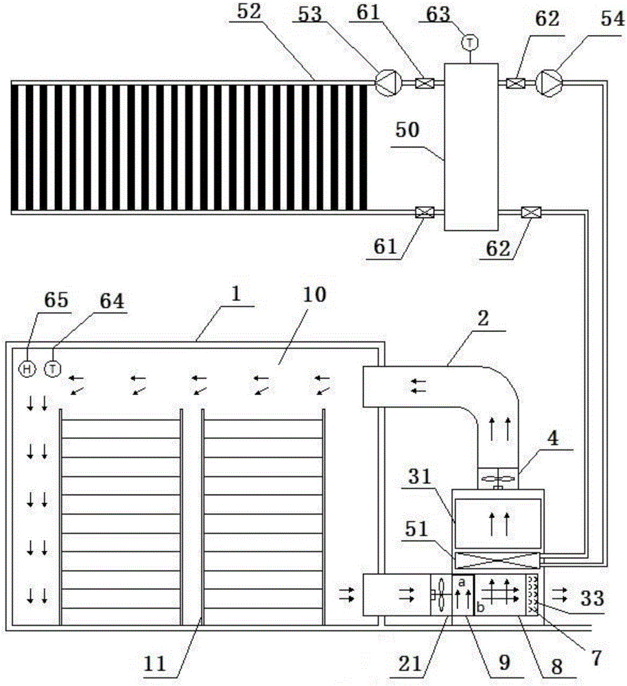
[0068] This embodiment provides a heat pump dryer, such as Figure 1-2 As shown, it includes: a drying room 1, which has a drying space 10, and an air inlet and an air exhaust port communicated with the drying space 10. The drying room 1 is provided with a drying room for placing articles to be dried. Shelves 11; air supply channel 2, communicated with the air inlet of the drying room 1; heat pump system, with a condenser 31, and the condenser 31 is used to heat the air entering the air supply channel 2; condensing fan 4 , installed inside the air supply channel 2, used to drive the air in the air supply channel 2 to flow to the air inlet of the drying room 1 after passing through the condenser 31; also includes: a solar heating system, with The heat dissipation coil 51 is installed upstream of the condenser 31 , so that the air can enter the drying room 1 after being heated by the heat dissipation coil 51 and the condenser 31 in sequence.

[0069] According to the technical ...


PUM


Abstract

The invention provides a heat pump dryer. The heat pump dryer comprises a drying chamber, an air supply channel, a heat pump system, a condensation fan and a solar heating system, wherein the drying chamber is provided with a drying space as well as an air inlet and an exhaust outlet which communicate with the drying space; the air supply channel communicates with the air inlet of the drying chamber; the heat pump system is provided with a condenser; the condenser is used for heating air entering the air supply channel; the condensation fan is arranged inside the air supply channel and is used for driving the air in the air supply channel to pass through the condenser and then to flow towards the air inlet of the drying chamber; the solar heating system is provided with a heat radiation coiled tube; and according to the mounting position of the heat radiation coiled tube, the air is enabled to pass through the heat radiation coiled tube, is heated by the condenser and then enters the drying chamber in sequence. According to the heat pump dryer provided by the invention, the heat pump system is originally combined with the solar heating system, so that solar energy can be utilized to the maximum; and when outside sunlight is insufficient, energy is supplemented by means of a heat pump, and thereby the heating efficiency for the air is not reduced, and energy conservation and emission reduction can be realized to the maximum.

Description

technical field [0001] The invention relates to the technical field of heat pump drying, in particular to a heat pump dryer. Background technique [0002] The principle of the heat pump dryer is the reverse Carnot principle. The gas is pressurized in the compressor to become a high-temperature and high-pressure gas, and then enters the condenser. In the condenser, the refrigerant condenses and liquefies, releasing heat to increase the air in the drying room. temperature. The materials in the drying room vaporize and evaporate the moisture in the materials in the form of hot air, and the evaporated water vapor is discharged by the dehumidification system to achieve the purpose of drying the materials. Existing heat pump dryers currently on the market generally discharge high-temperature water vapor directly from the dehumidification system, resulting in a waste of energy. [0003] Chinese patent document CN204902531U discloses a heat pump drying device that can realize humi...

Claims


Application Information

Patent Timeline
Patent Type & Authority Applications(China)
IPC IPC(8): F26B9/02F26B21/00F26B21/10F26B21/12F26B23/00F24J2/24F25B30/02F24S10/70
CPCF24S10/70F25B30/02F26B9/02F26B21/002F26B21/10F26B21/12F26B23/00Y02E10/44
Inventor 王立乾林丹
Owner GREE ELECTRIC APPLIANCES INC
Why Eureka
Try Eureka