Testing method for coaxiality of flanges at two ends of pipeline valve

A detection method and coaxiality technology, applied in the detection field, can solve problems such as damage to the three-coordinate measuring machine platform, inability to guarantee coaxiality detection, unfavorable mass detection, etc., achieve good practicability and economy, and reduce labor Strength, low cost effect

Active Publication Date: 2017-04-26
HENAN INST OF ENG
View PDF17 Cites 5 Cited by
  • Summary
  • Abstract
  • Description
  • Claims
  • Application Information

AI Technical Summary

Problems solved by technology

At present, some production enterprises do not have three-coordinate measuring machine equipment, which leads to the lack of this detection; some production enterprises use three-coordinate measuring machine for detection, because three-coordinate measuring Conditions such as constant voltage, in actual production, are not conducive to mass testing and affect the production cycle
Due to the large size and heavy weight of some pipeline valves, it is difficult to operate during use, which can easily cause damage to the three-coordinate measuring machine platform and low labor efficiency.
Since some pipeline valves have a diameter of 24-36 inches, they cannot be moved to the three-coordinate measuring machine platform so that they cannot be detected
Pipeline valve manufacturers cannot guarantee that 100% of the valves produced will be tested for coaxiality, and they will not be able to guarantee that the valves that have not been tested for coaxiality meet the requirements of Article 7.7.1.4 of API6D-2008

Method used


Image

  • Testing method for coaxiality of flanges at two ends of pipeline valve
  • Testing method for coaxiality of flanges at two ends of pipeline valve
  • Testing method for coaxiality of flanges at two ends of pipeline valve

Examples


Embodiment Construction

[0016] In the following description, for purposes of explanation, numerous specific details are set forth in order to provide a thorough understanding of one or more embodiments. It may be evident, however, that these embodiments may be practiced without these specific details.

[0017] Various embodiments according to the present invention will be described in detail below with reference to the accompanying drawings.

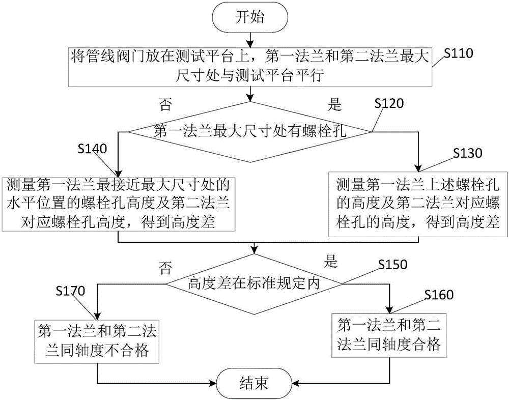
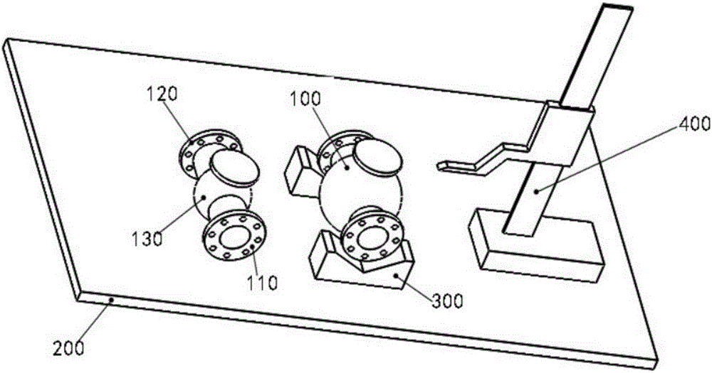
[0018] figure 1 It is a flow chart of the method for detecting the coaxiality of flanges at both ends of the pipeline valve of the present invention, figure 2 It is a schematic diagram of the method for detecting the coaxiality of flanges at both ends of the pipeline valve of the present invention, as figure 1 with 2 As shown, the method for detecting the coaxiality of flanges at both ends of the pipeline valve includes:

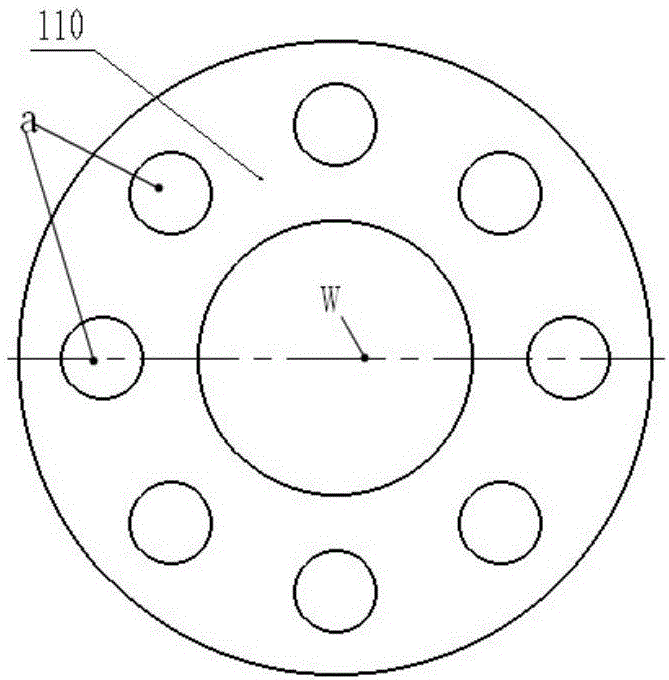
[0019] In step S110, the two ends of the pipeline valve 100 are symmetrically provided with a first flange 110 and a second flange 120,...


PUM


Abstract

The invention provides a testing method for coaxiality of flanges at two ends of a pipeline valve. The method comprises the steps of symmetrically arranging a first flange and a second flange at two ends of the pipeline valve, and placing the first flange and the second flange on a testing platform; determining whether a bolt hole exists at a maximal dimension position of the first flange; if yes, measuring the height of the bolt hole on the first flange and the height of the bolt hole on the second flange, and obtaining a height difference of each pair of symmetrical bolt holes on the positions of the first flange and the second flange; if otherwise, measuring the height of the bolt hole at a horizontal position which is nearest to the maximal dimension position on the first flange and the height of the bolt hole that corresponds with the second flange, thereby obtaining a height difference of each pair of symmetrical bolt holes on the first flange and the second flange; determining whether the height difference is in a preset standard; if yes, determining qualification of the coaxility between the first flange and the second flange; and otherwise, determining unqualification of the coaxility between the first flange and the second flange. The testing method can test all pipeline valves with different dimensions and furthermore has advantages of low requirement for a testing environment, high testing speed and low cost.

Description

technical field [0001] The invention relates to the technical field of detection, and more specifically, to a method for detecting the concentricity of flanges at both ends of a pipeline valve. Background technique [0002] The pipeline valve needs to be connected with the pipeline, and the valve end flange and the pipeline flange are tightly connected by bolts. In order to enable the pipeline valve to be connected to the pipeline normally, API (American Petroleum Institute) 6D-2008 puts forward specific requirements for the coaxiality of the flange bolt holes at both ends of the pipeline valve (Article 7.7.1.4 of API6D-2008), That is, for valves with a specification of DN100 (NPS4) and below, the maximum allowable displacement of the bolt hole shall not exceed 2mm (0.079 inches), and for valves with specifications above DN100 (NPS4), the maximum allowable displacement of the bolt hole shall not exceed 3mm ( 0.118 inches). [0003] Domestic pipeline valves are all manually...

Claims


Application Information

Patent Timeline
Patent Type & Authority Applications(China)
IPC IPC(8): G01B5/252G01B11/27
CPCG01B5/252G01B11/27
Inventor 尹建云方圣莹陶忭方明
Owner HENAN INST OF ENG
Why Eureka
Try Eureka