Supercharge Your Innovation With Domain-Expert AI Agents!

Periodic motion observation system

A technology of periodic motion and observation system, applied in the parts of TV system, TV, optics, etc., can solve the problems of high price, increased observation cost, difficult to observe observation objects, etc., to achieve the effect of cost suppression and easy discovery

Inactive Publication Date: 2017-04-26
SUNKIKO
View PDF7 Cites 0 Cited by
  • Summary
  • Abstract
  • Description
  • Claims
  • Application Information

AI Technical Summary

Problems solved by technology

However, this kind of high-speed camera is expensive, and it is difficult to easily observe the observation object in periodic motion, which has the problem of increasing the observation cost

Method used


Image

  • Periodic motion observation system
  • Periodic motion observation system
  • Periodic motion observation system

Examples


Embodiment Construction

[0036] Next, refer to Figure 1 to Figure 11 An embodiment of the periodic motion observation system of the present invention will be described.

[0037] [overall composition]

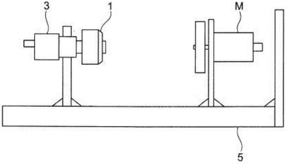
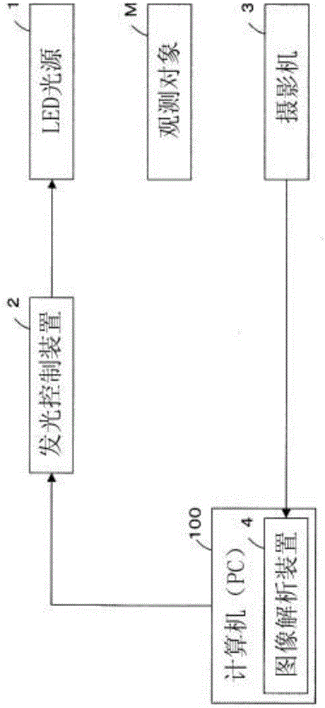
[0038] figure 1 It is a schematic diagram showing the mechanical constitution of the periodic motion observation system (hereinafter referred to as the system) of the present embodiment. figure 2 Then it is the block diagram of the circuit structure of this system.

[0039] This system is used to observe the rotation status of a DC motor that rotates at a high speed with a predetermined period as the observation object M. It has: an LED light source 1 that emits a flash at a predetermined period and illuminates the observation object; a light-emitting control device 2 for Controlling the light-emitting period and light-emitting time of the LED light source 1; the camera 3 photographs the observation object M that is irradiated by the LED light source 1; and the image analysis device 4 analyzes the...


PUM


Abstract

The purpose of the present invention is to provide a periodic motion observation system, made to a simple configuration, with which it is possible to specify with high accuracy the locus, speed, and a place in which strain, etc., has occurred in the periodic motion of an object to be observed. A flash light is emitted every prescribed period from a light source 1 and the periodic motion at a prescribed observation point of an object M to be observed is image-captured by an image-capturing camera 3, and then the image pertaining to the periodic motion at the prescribed observation point of the object M to be observed that was captured by the image-capturing camera 3 is analyzed by an image analysis device 4. This image analysis unit 4 extracts, on the basis of the image pertaining to the periodic motion at the prescribed observation point of the object M to be observed, the coordinates of the prescribed observation point at a time when the prescribed observation point of the object M to be observed is irradiated by the light source, and outputs each of the coordinates in tabular form or graphic form.

Description

technical field [0001] The present invention relates to a periodic motion observation system for observing the periodic motion of a predetermined observation point as an observation object by emitting a flash light from a light source and irradiating it on the observation object in periodic motion. Background technique [0002] When the light source emits a flash of light for an instant, and at the same time repeatedly emits the flash of light at a certain period, and illuminates the observation object in periodic motion, the observation object is in a static state or in a slow motion state of slow motion. The strobe effect has been used in various fields. Objects of observation include, for example, a motor that rotates at a high speed at a constant cycle, a printer that discharges liquid droplets at a constant cycle and travels at a predetermined speed, a fuel ejection device, and the like. [0003] However, a method using a so-called high-speed camera is known as a metho...

Claims


Application Information

Patent Timeline
IPC IPC(8): H04N5/225G03B15/00G03B15/05H04N5/232
CPCG03B15/00G03B15/05H05B47/16H05B47/125Y02B20/40H04N23/00H04N23/60H04N23/56H04N23/6811H04N23/80H04N9/3155
Inventor 高山满林泰彦
Owner SUNKIKO
Features
  • R&D
  • Intellectual Property
  • Life Sciences
  • Materials
  • Tech Scout
  • Unparalleled Data Quality
  • Higher Quality Content
  • 60% Fewer Hallucinations
Learn More