
Continuous fiber bundle multi-layer co-extrusion head die

A continuous fiber and co-extrusion technology, applied in the field of continuous fiber bundle multi-layer co-extrusion dies, can solve the problems of easy separation of fibers and resins, long pipe production lines, and low service life of products, and achieve fiber modification The effect is remarkable, the process operation is simple, and the flow channel design is reasonable.

Active Publication Date: 2017-05-03
SHANGHAI QINGYUAN PIPE TECH
View PDF7 Cites 3 Cited by
  • Summary
  • Abstract
  • Description
  • Claims
  • Application Information

AI Technical Summary

Problems solved by technology

This production method has the following disadvantages: (1) product limitations, it can only be realized on solid-walled and circular plastic pipes, and cannot be applied to hollow-walled plastic pipes, especially in I-beam and corrugated pipes. , ring-shaped rib-shaped structural wall pipe; (2) low production efficiency, long pipe production line, various equipment, long production cycle, and difficult stable control of product quality; (3) high production energy consumption, the pipe molding needs 2 times Molding process; (4) The bonding force between fiber and resin is limited, and fiber and resin are easy to peel off each other when subjected to external force, and the service life of the product is low
However, the biggest problem with this production method is that the continuous long fibers are cut into short fibers of 3 to 5 mm, which greatly reduces the room for improving the impact strength and tensile strength of the pipe.

Method used


Image

  • Continuous fiber bundle multi-layer co-extrusion head die
  • Continuous fiber bundle multi-layer co-extrusion head die
  • Continuous fiber bundle multi-layer co-extrusion head die

Examples


Embodiment Construction

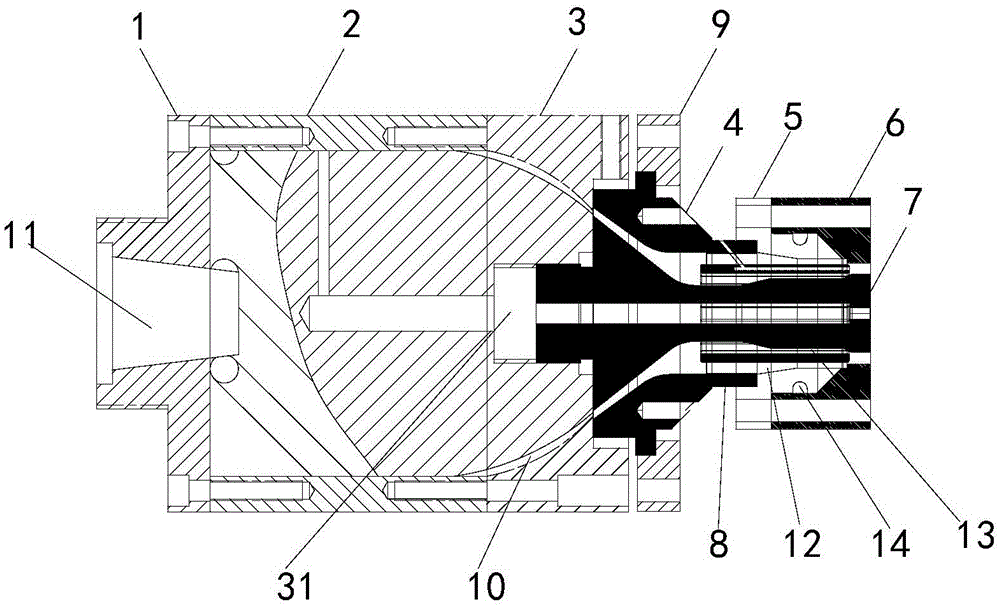
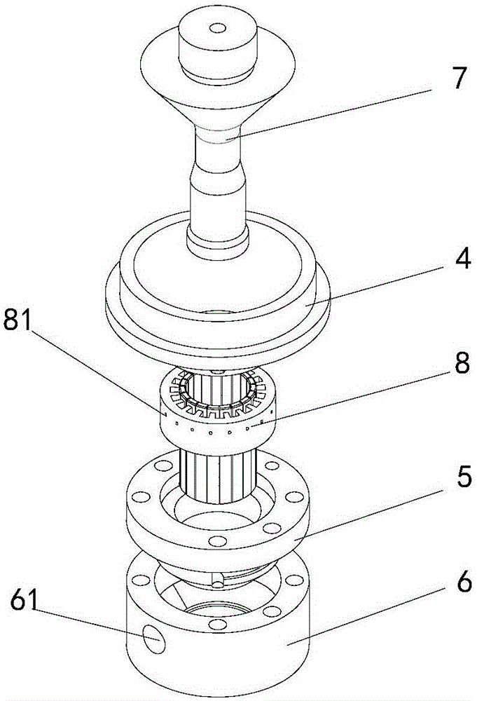
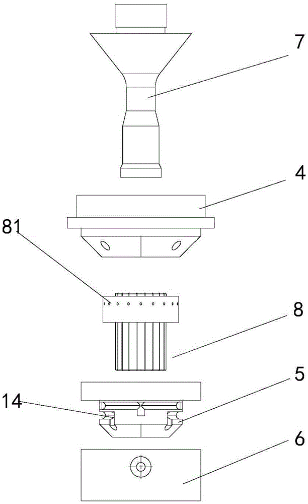
[0024] see figure 1 , with reference to figure 2 , image 3 , the continuous fiber bundle multi-layer co-extrusion head die of the present invention includes a composite die head formed by sequentially connecting the first die head 1, the second die head 2 and the third die head 2, and the first die head arranged in sequence A composite outer mold composed of an outer mold 4 , a second outer mold 5 and a third outer mold 6 , as well as a core mold 7 , a die 8 and a die platen 9 .

[0025] The composite die is used to be connected with the main extruder, and the composite die is provided with a main flow channel 10 for communicating with the main extruder; wherein the first die 1 is provided with a main material channel 10 for communicating with the main extruder. The main feed port 11, the third die head 3 is provided with an internal thread hole 31 for the screw connection of the mandrel; the resin from the main extruder enters the main material flow channel through the ma...


PUM


Abstract

A continuous fiber bundle multi-layer co-extrusion head die comprises a compound die head used for being connected with a main extruder, a compound outer die used for being connected with an auxiliary extruder, a core die, a mouth die and a die head pressing plate. The compound die head is provided with a main material runner used for communicating with the main extruder. The compound outer die is provided with an auxiliary material runner used for communicating with the auxiliary extruder. A first runner is formed between the mouth die and the compound outer die, and a second runner is formed between the mouth die and the core die. A continuous fiber bundle enters a filament penetrating channel through a filament penetrating hole in the mouth die, intersects with resin from the main material runner and the auxiliary material runner at the port of the mouth die and is evenly wrapped by the resin, and a multi-layer compound structure is formed. The continuous fiber bundle multi-layer co-extrusion head die has the beneficial effects that the application range is wide, high efficiency and energy saving are achieved, the technology operation is simple, fiber bundles are arranged in order, and the fiber modification effect is obvious.

Description

technical field [0001] The invention relates to a mold, in particular to a continuous fiber bundle multi-layer co-extrusion head mold. Background technique [0002] Plastic pipes have the advantages of light weight, corrosion resistance, and long service life, but compared with traditional pipes (such as concrete pipes, etc.), there is a certain gap in service strength. This defect greatly limits the promotion and application of plastic pipes. Fiber has the characteristics of high strength, wear resistance, and good impact resistance, so it is often used in the reinforcement and modification of plastic pipes, especially the reinforcement and toughening modification of plastic pipes by adding continuous fiber bundles. [0003] Invention patent CN201293157Y discloses a "PE wound composite pipe". The production steps of the continuous fiber bundle reinforced plastic pipe mentioned in the patent are as follows: firstly, the inner embryo of the circular pipe is extruded through...

Claims


Application Information

Patent Timeline
IPC IPC(8): B29C47/12B29C48/30
CPCB29C48/30
Inventor 苏长裕杨永喆沈佳俊
Owner SHANGHAI QINGYUAN PIPE TECH
Features
  • Generate Ideas
  • Intellectual Property
  • Life Sciences
  • Materials
  • Tech Scout
  • Unparalleled Data Quality
  • Higher Quality Content
  • 60% Fewer Hallucinations
Learn More