Elastic bone screw

A bone screw and elastic technology, applied in the field of bone screws, can solve problems such as reduced friction, difficulty in forming a dynamic elastic structure, deformation or fracture of steel plates, etc., and achieves the effects of increased welding reliability, increased torsional force, and less breakage

Active Publication Date: 2017-05-10
DABO MEDICAL TECH CO LTD
View PDF7 Cites 8 Cited by
  • Summary
  • Abstract
  • Description
  • Claims
  • Application Information

AI Technical Summary

Problems solved by technology

However, the traditional steel plate mainly relies on the friction force of the interface between the bone and the steel plate to realize the pressure of the steel plate on the bone. As the axial dynamic load cycle increases, the screw begins to loosen and the friction force decreases, and the steel plate finally fixed at the fracture site is thus loose
If this loosening occurs before the fracture has healed, instability will occur at the fracture site, which may eventually lead to deformation or fracture of the plate, and in fracture sites where it is more difficult to obtain screw fixation to maintain fixation (such as metaphyseal or bone fractures). loose bone end), it will be more prone to instability at the fracture site
At the same time, while applying traditional steel plates, the researchers also found that the fracture site where traditional steel plates are applied will produce first-line biological defects: compressing the periosteum and affecting the blood supply to the fracture site and / or end
Although the above-mentioned technology can promote the formation of callus and accelerate the healing of biological fractures through the micro-movement caused by the dynamic elastic structure of the threaded sleeve, when the fixation screw is screwed into the bone on both sides of the fracture through the threaded sleeve, the two are easy. Secured together by interfitting threads, it is difficult to form a dynamic elastic structure, which does not promote callus formation, and thus functions as a single locking screw

Method used


Image

  • Elastic bone screw
  • Elastic bone screw
  • Elastic bone screw

Examples


Embodiment 1

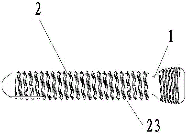
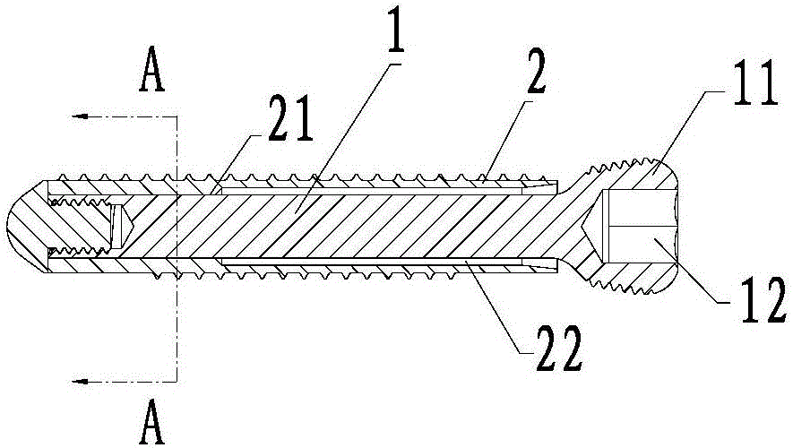
[0034] refer to Figure 1-8 , an elastic bone screw, comprising an elastic rod 1 and a limiting sleeve 2; a part of the elastic rod 1 is inserted into the limiting sleeve 2 along the axial direction of the limiting sleeve 2; one end of the elastic rod 1 It is fixedly connected with the slot 21 in the limiting sleeve 2, and the other end is provided with a locking joint 11, and the end surface of the locking joint 11 along the axial direction is provided with a screw groove 12; the outer periphery of the limiting sleeve 2 is provided with There are 23 threads. The rotation of the elastic rod 1 drives the limit sleeve 2 to rotate, so that the thread 23 on the outer periphery of the limit sleeve 2 is fixed and locked with the fracture.

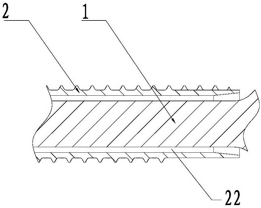
[0035] In the part where the elastic rod 1 is inserted into the limit sleeve 2, there is a limit gap 22 between the other positions and the inner wall of the limit sleeve 2 except the position fixedly connected with the limit sleeve 2; During h...

Embodiment 2

[0044] refer to Figure 9 The difference between this embodiment and embodiment 1 is that the cross section of the part where the elastic rod 1 is fixedly connected with the limiting sleeve 2 is triangular.

Embodiment 3

[0046] refer to Figure 10 The difference between Example 1 and Example 1 is that the cross-section of the part where the elastic rod 1 is fixedly connected with the limit sleeve 2 is quincunx-shaped.


PUM


Abstract

The invention provides an elastic bone screw. At the position where an elastic rod and a limiting sleeve are fixedly connected, ribs distributed at intervals are arranged at the circumstantial direction, and the ribs protrude outward toward the direction close to the limiting sleeve; an inserting groove of the limiting sleeve forms concave grooves in the position corresponding to the ribs; when the elastic rod is fixedly connected to the limiting sleeve, the ribs and the grooves mesh in the rotating direction of the elastic rod to form a cooperatively limited helix resistance structure, and thus when the elastic rod rotates, no relative motion is conducted between the elastic rod and the limiting sleeve in the rotating direction; the elastic rod is inserted into the part of the limiting sleeve, and the tail end face of the part and the tail end face of the limiting sleeve are subjected to visual welding fixing. Through micro motion of the elastic bone screw, relative motion occurs between a locking plate and a connected bone in the direction parallel with the initial installing position, and healing of the bone is better promoted. Moreover, due to the use of the visual welding, the limiting sleeve and the elastic rod are welded, and the problems in the traditional blind welding process of pseudo soldering and solder skips can be effectively avoided.

Description

technical field [0001] The invention relates to a medical device, in particular to a bone screw. Background technique [0002] The traditional method of fracture treatment is to fix the steel plate on the fracture, so that the two ends of the fracture can re-grow, and try to restore the original appearance and performance of the bone under the protection of the steel plate. However, the traditional steel plate mainly relies on the friction force of the interface between the bone and the steel plate to realize the pressure of the steel plate on the bone. As the axial dynamic load cycle increases, the screw begins to loosen and the friction force decreases, and the steel plate finally fixed at the fracture site is thus loose. If this loosening occurs before the fracture has healed, instability will occur at the fracture site, which may eventually lead to deformation or fracture of the plate, and in fracture sites where it is more difficult to obtain screw fixation to maintain...

Claims


Application Information

Patent Timeline
Patent Type & Authority Applications(China)
IPC IPC(8): A61B17/86
CPCA61B17/86A61B17/8605A61B17/861A61B17/8625A61B2017/564A61B2017/8655
Inventor 陈晋伟刘崇兵
Owner DABO MEDICAL TECH CO LTD
Why Eureka
Try Eureka