
Process device for collecting and purifying chemical tail gas of storage tank

A technology of chemical tail gas and purification process, which is applied in the direction of gas treatment, steam condensation, chemical instruments and methods, etc. It can solve the problems affecting the safety and stability of on-site operations, affecting the physical and mental health of employees, and the large amount of volatile gas, so as to promote clean production , improve the surrounding environment, low investment effect

Pending Publication Date: 2017-05-10
SHANDONG IRON & STEEL CO LTD
View PDF5 Cites 0 Cited by
  • Summary
  • Abstract
  • Description
  • Claims
  • Application Information

AI Technical Summary

Problems solved by technology

[0002] In the production system of the coking plant, various storage tanks are used to store raw materials or products, and a release pipe is generally provided on the top of the storage tank to prevent the tank body from being deformed due to excessive or low pressure inside the storage tank; because the material in the storage tank If there is a certain temperature or volatile substances, a mixed vapor phase such as tar, benzene, naphthalene, water, etc. will continue to appear at the discharge pipe on the top of the storage tank. If these mixed vapor phases are not collected and purified, these volatiles will pollute the site Air, resulting in extremely poor production environment, affecting the physical and mental health of employees; when there is a large amount of volatile gas, it is inevitable that there will be pollution and flammable gases discharged, and there is a danger of flammability and explosion, which will affect the safety and stability of on-site operations

Method used


Image

  • Process device for collecting and purifying chemical tail gas of storage tank
  • Process device for collecting and purifying chemical tail gas of storage tank
  • Process device for collecting and purifying chemical tail gas of storage tank

Examples


Embodiment Construction

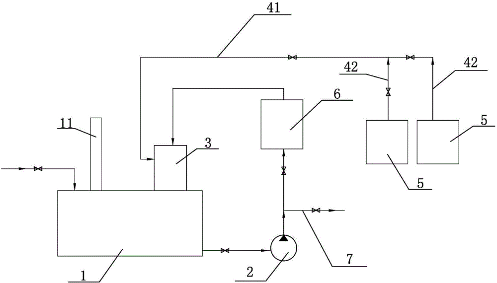
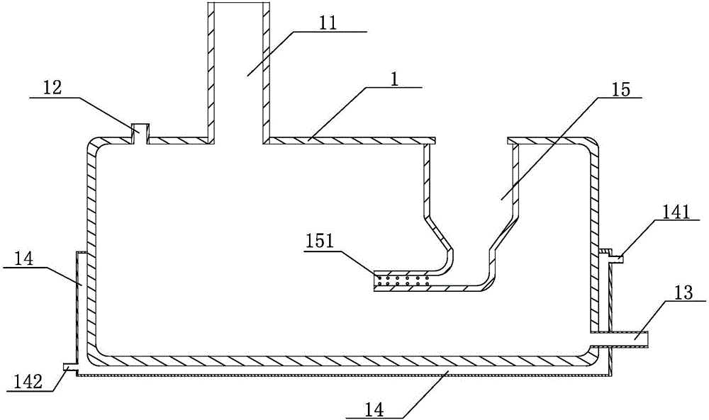
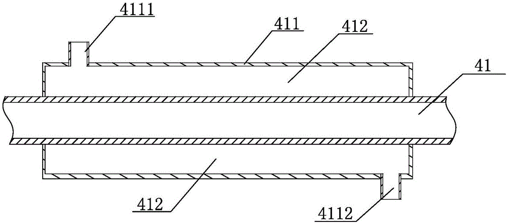
[0022] Below will combine specific embodiment and appended Figure 1-4 , clearly and completely describe the technical solutions in the embodiments of the present invention, obviously, the described embodiments are only some preferred embodiments of the present invention, not all the embodiments. Those skilled in the art can make similar modifications without departing from the connotation of the present invention, so the present invention is not limited by the specific embodiments disclosed below.

[0023] The invention provides a storage tank chemical tail gas collection and purification process device (such as figure 1 Shown), comprise tail gas collection pipeline, gas-liquid mixing device 3, spray liquid storage tank 1 and circulation pump 2, tail gas collection pipeline mainly is to complete the collection work of the chemical tail gas discharged in each storage tank, in this specific embodiment, The exhaust gas collection pipeline includes an exhaust gas confluence pipe...


PUM


Abstract

The invention provides a process device for collecting and purifying chemical tail gas of a storage tank. The process device comprises a tail gas collecting pipe, a gas-liquid mixing device, a spray liquid storage tank and a circulating pump, wherein the gas-liquid mixing device comprises a cylindrical shell, venturi tubes, a high-pressure liquid supply pipe and a tail gas suction pipe; a spray liquid inlet and a tail gas discharge pipe are arranged at the upper part of the spray liquid storage tank; the gas-liquid mixing device is arranged on the spray liquid storage tank and outlet ends of the two venturi tubes communicate with the inside of the spray liquid storage tank; the circulating pump is connected between the outlet end of the spray liquid storage tank and the inlet end of the high-pressure liquid supply pipe through a pipe in series; and the tail gas collecting pipe is connected with the tail gas suction tube. By using the purifying process device, collecting and processing of the chemical tail gas volatilizing from the storage tank in a production field can be achieved, so that the targets of purifying the work environment and ensuring safe production are achieved. According to the gas-liquid mixing device in the process device, adequate mixing of spray liquid and the tail gas can be achieved and the tail gas purifying quality is greatly improved.

Description

technical field [0001] The invention relates to a process device for collecting and purifying chemical tail gas in a storage tank. Background technique [0002] In the production system of the coking plant, various storage tanks are used to store raw materials or products, and a release pipe is generally provided on the top of the storage tank to prevent the tank body from being deformed due to excessive or low pressure inside the storage tank; because the material in the storage tank If there is a certain temperature or volatile substances, a mixed vapor phase such as tar, benzene, naphthalene, water, etc. will continue to appear at the discharge pipe on the top of the storage tank. If these mixed vapor phases are not collected and purified, these volatiles will pollute the site Air, resulting in extremely poor production environment, affecting the physical and mental health of employees; when there is a large amount of volatile gas, it is inevitable that polluting and flam...

Claims


Application Information

Patent Timeline
Patent Type & Authority Applications(China)
IPC IPC(8): B01D53/18B01D5/00
CPCB01D5/0057B01D53/002B01D53/18B01D2258/0283
Inventor 李瑞萍梁永飞魏纯玉牟振龙王爱霞
Owner SHANDONG IRON & STEEL CO LTD
Learn More