Automatic closed forging forming die

A technology of forming die and automatic blocking, which is used in manufacturing tools, forging/pressing/hammer devices, forging/pressing/hammering machines, etc., which can solve the problem of low unlocking flexibility of jaws, small size range of forgings, and locking accuracy. problems such as decline, to ensure the quality of forging, the forging process is easy to operate, and the effect of avoiding changes

Active Publication Date: 2017-05-10
ANHUI UNIVERSITY OF TECHNOLOGY
View PDF10 Cites 12 Cited by
  • Summary
  • Abstract
  • Description
  • Claims
  • Application Information

AI Technical Summary

Problems solved by technology

The application has a simple structure and can complete the two-way closed forging process; but the shortcoming of the application is that it only relies on the elastic element to provide the closed mold clamping pressure, the pressure is relatively small, and the size range of forgings suitable for production is small
In this application, an insert is arranged on the upper floating plate, and an inclined surface is provided on the insert. The friction with the insert increases the mold clamping force, but this application has the following disadvantages: (1) The locking force is provided by the cooperation between the claw and the slope of the insert, and the mating surface is severely worn during the continuous mold opening and closing process , leading to a decrease in subsequent locking accuracy; (2) The flexibility of claw unlocking is not high, and the risk of claws being locked and difficult to open the mold is prone to occur when the mold is opened, and further improvement is still needed

Method used


Image

  • Automatic closed forging forming die
  • Automatic closed forging forming die
  • Automatic closed forging forming die

Examples


Embodiment 1

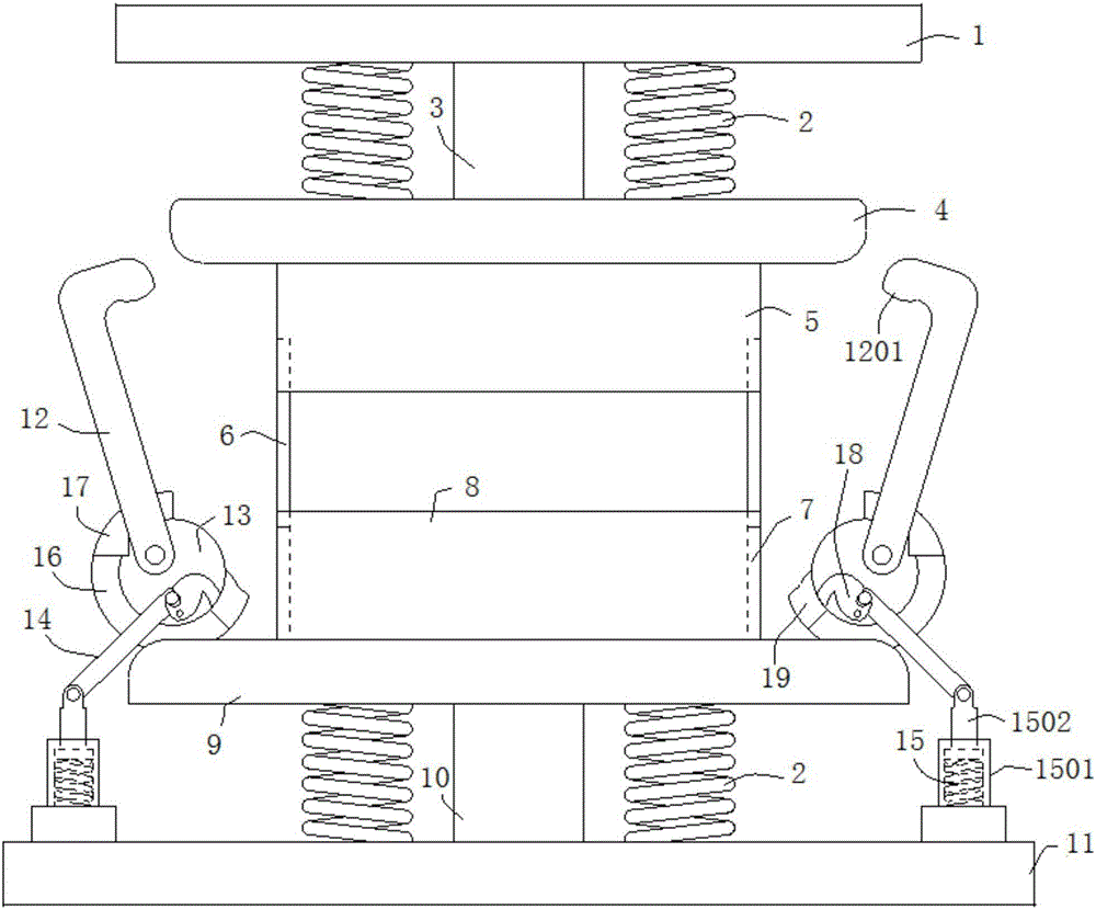
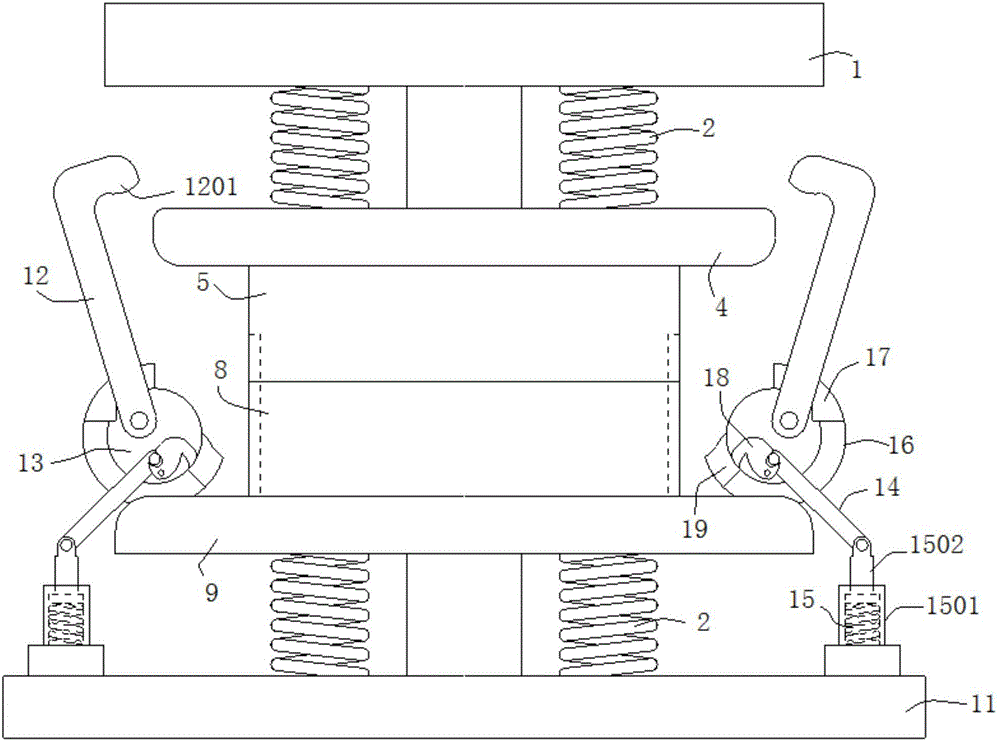
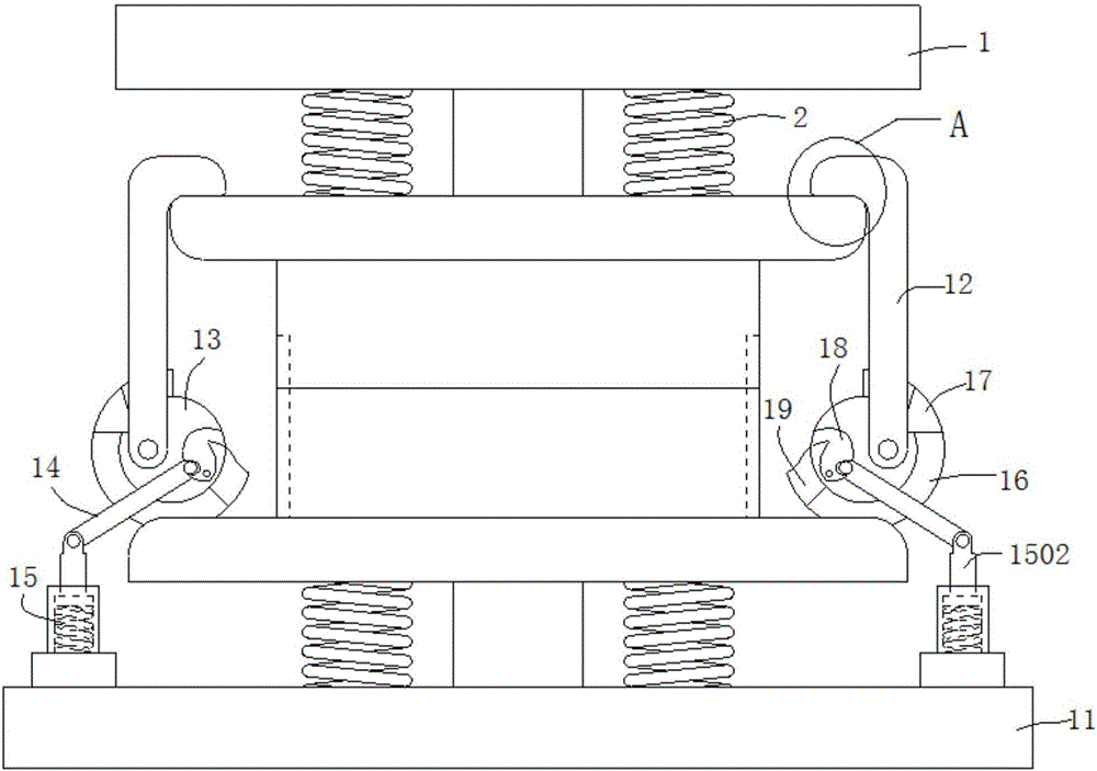
[0049] A kind of automatic occlusion forging forming die of this embodiment comprises rigid mold base, floating die and automatic clamping device, such as figure 1 As shown, the rigid die base includes an upper die base 1, an upper punch 3, a lower die base 11 and a lower punch 10, the upper punch 3 is fixedly installed on the upper die base 1, and the lower punch 10 is fixedly installed on the lower die base 11. The floating die includes an upper die holder 4, an upper die holder 5, a lower die holder 8 and a lower die holder 9, wherein the upper die holder 4 is floatingly connected with the upper die holder 1 through a mold spring 2, and the lower die holder The base 9 is floatingly connected with the lower mold base 11 through the mold spring 2. The mold spring 2 can be a metal coil spring, a nitrogen gas spring or a polyurethane spring. Specifically, in this embodiment, the mold spring 2 is a metal coil spring. The upper die 5 and the lower die 8 are correspondingly fixed ...

Embodiment 2

[0054] A self-closing forging forming die of this embodiment is basically the same as that of Embodiment 1. Further, the power mechanism in this embodiment includes a rotating disk 13, a driving connecting rod 14 and an elastic element 15, such as figure 1 As shown, the lower die base 9 is provided with a fixed seat 16, and the rotating disk 13 is movably arranged inside the fixed seat 16. Specifically, the fixed seat 16 is a ring concentric with the rotating disk 13, and the rotating disk 13 is embedded in the Inside the ring and capable of rotating around the center of the circle, the two axial ends of the fixed seat 16 are provided with limiting pieces, which extend toward the direction close to the rotating disk 13, and the limiting pieces surround the rotating disk 13 in the circumferential direction. Distributed at intervals, the limit piece clamps the rotating disc 13 in the fixed seat 16, and acts as an axial limit for the rotating disc 13, preventing the rotating disc ...

Embodiment 3

[0067] A self-blocking forging forming die of this embodiment is basically the same as that of Embodiment 2. Furthermore, in this embodiment, the locking hook 18 is connected with the rotating disk 13 through the third connecting shaft 1801, as Figure 9 , Figure 10 As shown, the locking hook 18 can rotate around the third connecting shaft 1801 , and the third connecting shaft 1801 is located at the center of the arc-shaped side wall of the above-mentioned arc-shaped sliding slot 1301 . When the second connecting shaft 1401 at one end of the driving link 14 slides along the arc-shaped chute 1301, the locking hook 18 is driven to rotate around the third connecting shaft 1801, so as to realize the cooperative locking or disengagement of the locking hook 18 and the locking block 19 , and connecting the lock hook 18 with the rotating disk 13 helps to improve the structural strength and structural stability of the lock hook 18, ensures the stability of its operation process, and m...


PUM


Abstract

The invention discloses an automatic closed forging forming die, and belongs to the technical field of metal press machining. The die comprises a rigid die base, a floating female die, and automatic die locking devices symmetrically arranged on the two sides of a lower female die base. The two sides of the upper end face of an upper female die base are symmetrically provided with clamping grooves. Each automatic die locking device comprises a swinging lock rod and a power mechanism driving the swinging lock rod to swing. Lock heads clamped to the clamping grooves in a matched mode are arranged on the tops of the swinging lock rods. During combination of an upper female die and a lower female die, the power mechanisms drive the swinging lock rods to swing in the direction close to the upper female die till the lock heads make contact with the clamping grooves to be clamped; During opening of the upper female die and the lower female die, the power mechanisms drive the swinging lock rods to swing in the direction away from the upper female die till the lock heads get away from the clamping grooves to be reset. The die clamping pressure can be increased, and automatic control over locking and unlocking of the upper and lower female dies of a die locking device is achieved.

Description

technical field [0001] The invention relates to the technical field of metal pressure processing, and more specifically relates to an automatic closing forging forming die. Background technique [0002] In recent years, closed forging, as a precision forging forming technology, has developed rapidly in the manufacturing of parts in the automotive, aerospace and other industries. The feature of this technology is that the mold is first closed and then the punch is used to extrude the billet in the die cavity, and the billet is in a three-dimensional compressive stress state with good plasticity through the mold clamping force and extrusion force, which can be formed in one time. Parts with large deformation, complex shape and high precision are obtained. Compared with the traditional open forging process, most of the cutting process is omitted, the production cost is low, and the material utilization rate is high. In the production process of some parts, especially for the ...

Claims


Application Information

Patent Timeline
Patent Type & Authority Applications(China)
IPC IPC(8): B21J13/02B21J5/02
CPCB21J5/025B21J13/02
Inventor 白凤梅李宁王景朱雷敏郑光文黄贞益刘相华胡晓安杨小杰任浩博屠静
Owner ANHUI UNIVERSITY OF TECHNOLOGY
Why Eureka
Try Eureka