Miniature drainage cover for local dry welding underwater robot of double-airflow structure

An underwater robot, local dry method, applied in gas flame welding equipment, welding equipment, metal processing equipment and other directions, can solve the problem of affecting the precise positioning of the welding robot's underwater torch, large engineering application limitations, and poor process adaptability. and other problems, to achieve the effect of improving the quality of underwater welding, improving the protection ability and reasonable structure

Active Publication Date: 2017-05-10
SOUTH CHINA UNIV OF TECH
View PDF7 Cites 14 Cited by
  • Summary
  • Abstract
  • Description
  • Claims
  • Application Information

AI Technical Summary

Problems solved by technology

However, generally speaking, the size of the local dry welding drainage cover at home and abroad is relatively large, which not only affects the precise positioning of the underwater welding torch of the welding robot, but also has great limitations in engineering applications, and poor adaptability to different positions of the process. Slow speed and low production efficiency

Method used


Image

  • Miniature drainage cover for local dry welding underwater robot of double-airflow structure
  • Miniature drainage cover for local dry welding underwater robot of double-airflow structure
  • Miniature drainage cover for local dry welding underwater robot of double-airflow structure

Examples


Embodiment 1

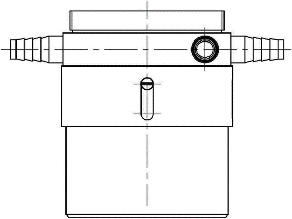
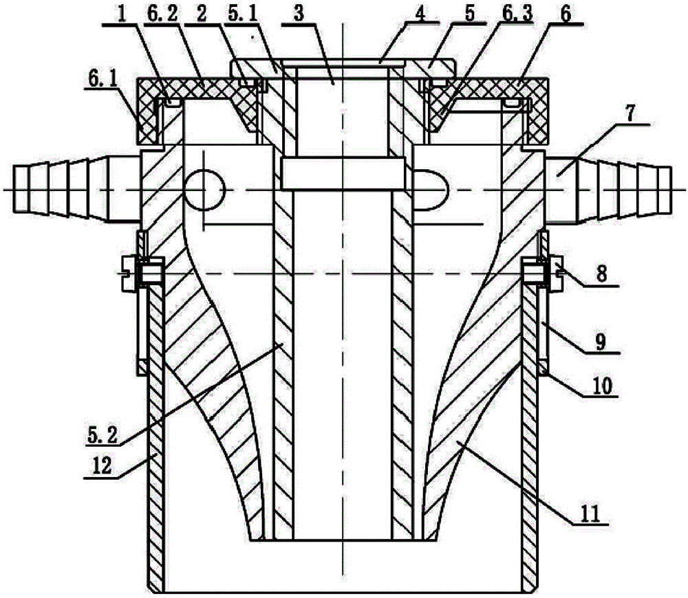
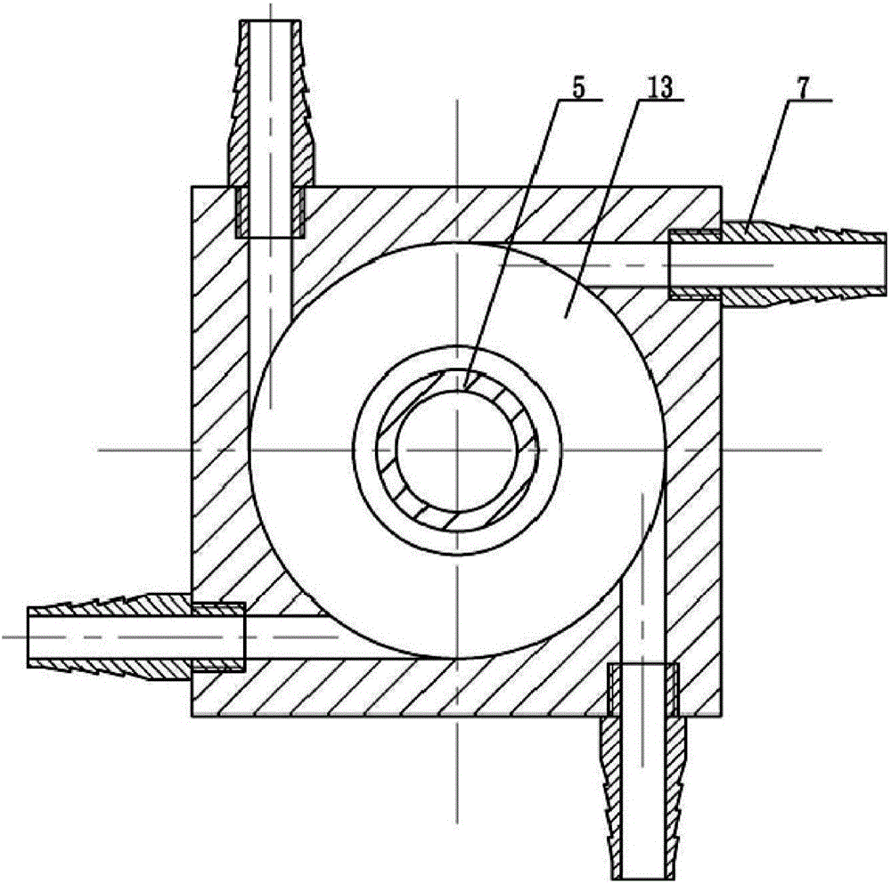
[0028] Such as Figure 1 ~ Figure 3 As shown, the partial dry-process underwater robot welding micro-drainage cover of this embodiment includes an inner air cover 5, an outer air cover 11 and a water retaining jacket 12 arranged in sequence from the inside to the outside. A welding torch installation hole 3 for setting a welding torch is formed inside the inner gas cover 5; the wall of the welding torch installation hole 3 is provided with an internal thread for installing a welding torch. A convergent shrinking nozzle cavity 13 is formed between the outer air cover 11 and the inner air cover 5; the top cover of the shrinking nozzle cavity 13 is provided with a sealing cover 6; the outer air cover 11 is connected with four air intake pipes 7; The lumens of each intake pipe 7 communicate with the contracting nozzle cavity 13 to realize the input of compressed gas. The water blocking jacket 12 is made of flexible high temperature resistant composite material. The water retaini...

Embodiment 2

[0041] In this embodiment, the double airflow structure local dry process underwater robot welding miniature drainage cover, such as Figure 4 As shown, it is applied to underwater fillet welding. During underwater fillet welding, the workpieces are perpendicular to each other, and the water retaining sleeve 12 is cut into a V shape according to actual requirements to adapt to actual engineering applications. The rest of the structure of this embodiment is the same as that of Embodiment 1.


PUM


Abstract

The invention provides a miniature drainage cover for a local dry welding underwater robot of a double-airflow structure. The miniature drainage cover is characterized by comprising an inner air cover, an outer air cover and a water retaining sleeve, wherein the inner air cover, the outer air cover and the water retaining sleeve are arranged in sequence from inside to outside; a welding torch mounting hole which is used for arranging a welding torch is formed in the inner air cover; a convergent nozzle cavity is formed between the outer air cover and the inner air cover; a sealing cover covers the top of the convergent nozzle cavity; at least one air inlet pipe is connected with the outer air cover; a pipe cavity of the at least one air inlet pipe communicates with the convergent nozzle cavity so as to input compressed gas; the water retaining sleeve is connected with the outer air cover so as to form a slag discharge cavity; and the lower part of the welding torch mounting hole and the lower part of the convergent nozzle cavity respectively communicate with the slag discharge cavity. The drainage cover has the advantages of reasonable structure, small size and flexibility in use and has a good drainage effect and a preventive effect on a welding area, and the underwater welding quality can be increased.

Description

technical field [0001] The invention relates to the technical field of welding equipment for underwater robots, and more specifically relates to a miniature drainage cover for welding underwater robots with a dual-airflow structure and local dry method. Background technique [0002] With the rapid development of the national economy and the urgent needs of energy strategies, a large number of marine engineering construction and nuclear power plant equipment maintenance require underwater welding operations. As one of the key technologies of ocean engineering, underwater welding has attracted much attention. From the installation and construction of offshore oil and gas platforms to the laying and maintenance of submarine pipelines, from the emergency repair of large ships to the repair of spent fuel pools in nuclear power plants, underwater welding operations are more and more widely used. [0003] At present, the underwater welding methods mainly include three methods: wet...

Claims


Application Information

Patent Timeline
Patent Type & Authority Applications(China)
IPC IPC(8): B23K5/02B23K5/24
CPCB23K5/02B23K5/24
Inventor 王振民谢芳祥朱磊
Owner SOUTH CHINA UNIV OF TECH
Why Eureka
Try Eureka