A kind of friction stir spot welding machine and friction stir spot welding method

A friction stir and spot welding technology, which is applied in the field of friction stir spot welding and friction stir spot welding, can solve the problems of unfavorable performance and breakage of friction stir spot welding joints, and achieves reduced deformation, reduced width difference, and reduced flying edge effect

Active Publication Date: 2018-11-23
SHENYANG AEROSPACE UNIVERSITY
View PDF9 Cites 0 Cited by
  • Summary
  • Abstract
  • Description
  • Claims
  • Application Information

AI Technical Summary

Problems solved by technology

During the process of pinning down the stirring pin, the material flows upward from the bottom of the stirring pin driven by the thread, and the material flowing upward will squeeze the contact surface between the upper plate and the lower plate, causing the lap interface and the upper plate to warp upward; the shaft shoulder After contacting the upper plate, it starts to squeeze the upper plate and move down, causing the original interface to "break off", thus forming a secondary hook defect
The appearance of secondary hook-shaped defects increases the way for crack propagation, which is extremely detrimental to the performance of friction stir spot welded joints

Method used


Image

  • A kind of friction stir spot welding machine and friction stir spot welding method
  • A kind of friction stir spot welding machine and friction stir spot welding method
  • A kind of friction stir spot welding machine and friction stir spot welding method

Examples


Embodiment 1

[0030] The operation steps are as follows:

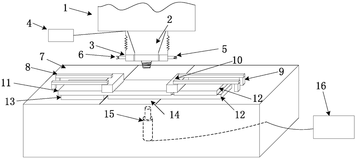
[0031] Step 1. Overlap the parts to be welded on the upper plate 11 and the lower plate 12 of the workpiece to be welded (the aluminum alloy plate), and fix them with a pressing block 10, a bead 8, a supporting block 9, a spacer 13 and a backing plate 14 On workbench 7. .In order to prevent the moving shoulder (not shown) of the mixing head from contacting with the stationary shoulder, and minimize material entering the gap, the gap between the stationary shoulder and the moving shoulder is selected as 0.1mm.

[0032] Step 2. Install an ultrasonic vibration device at the lower part of the workpiece welding area. The ultrasonic vibration device is composed of an ultrasonic generator 16, an ultrasonic transducer and an ultrasonic horn 15, wherein the ultrasonic horn is in contact with the lower plate of the workpiece.

[0033] Step 3. Use the above-mentioned ultrasonic vibration device to assist friction stir spot welding:

[0034] ...

Embodiment 2

[0038] The difference between this embodiment and embodiment 1 is that the rotation speed of the stirring head described in step 3 is 2000 rpm, and the others are the same as embodiment 1.

Embodiment 3

[0040] The difference between this embodiment and embodiment 1 is that the ultrasonic frequency described in step 3 is 60KHz, and the others are the same as embodiment 1.


PUM

PropertyMeasurementUnit
thicknessaaaaaaaaaa
thicknessaaaaaaaaaa

Abstract

The invention relates to a stirring friction spot welder. A static shaft shoulder is driven to move up and down by an independent motor; a cooling medium channel is arranged at the bottom of the static shaft shoulder; the cooling medium channel is closed by a bottom cap which is made from a high heat conductivity sheet metal. When the stirring friction spot welder is used for performing stirring friction spot welding, the motor can apply pressure to a workpiece in a manner of driving the static shaft shoulder to move downward and the cooling medium can cool the surface of a welding area; an ultrasonic generator arranged on the lower part of the workpiece is utilized to vibrate the workpiece surface; a stirring head is rotated and is downward penetrated through an upper plate; after the stirring head is downward penetrated through the upper plate, the stirring head is remained for a period of time and then is pulled back; after the cooling medium is continuously applied for a period of time, the static shaft shoulder is retracted and is out of contact with the workpiece; the ultrasonic vibration is kept for a period of time and then is stopped. The stirring friction spot welder has the beneficial effects that the welding area is free from secondary hooked defect and deformation, the material flow at the bottom of the welding core is enhanced, the atomic diffusion behavior is improved, the residual stress is reduced and the mechanical property of the joint is excellent.

Description

technical field [0001] The invention relates to friction stir welding, in particular to a friction stir spot welding machine with a cooling-controlled static shoulder and a method for using the spot welding machine to perform friction stir spot welding. Background technique [0002] Friction stir spot welding (FSSW) is a solid phase point connection technology developed on the basis of friction stir welding (FSW). Because FSSW has the advantages of simple process, energy saving, stable welding quality, high joint performance and small deformation, it has broad application prospects in aviation, aerospace, automobile, shipbuilding and other manufacturing industries. Friction stir spot welding includes three processes: 1. The lowering of the rotating stirring head; 2. Staying for a certain period of time after the lowering; 3. Pulling back the stirring head to complete the welding. [0003] Welding with the existing friction stir spot welding machine and welding process, duri...

Claims


Application Information

Patent Timeline
Patent Type & Authority Patents(China)
IPC IPC(8): B23K20/12
CPCB23K20/127
Inventor 岳玉梅姬书得周振鲁马琳张利国吕赞
Owner SHENYANG AEROSPACE UNIVERSITY
Why Eureka
Try Eureka