Optical fiber cutting device and method based on ultra-short pulse lasers

An ultra-short pulse laser and cutting device technology, which is applied in laser welding equipment, welding equipment, metal processing equipment, etc., can solve the problems of secondary damage to the optical fiber end face, inability to cut the optical fiber obliquely, and difficulty in obtaining the optical fiber end face, etc. The effect of deformation, simple device structure and convenient operation

Inactive Publication Date: 2017-05-10
XI AN JIAOTONG UNIV
View PDF10 Cites 10 Cited by
  • Summary
  • Abstract
  • Description
  • Claims
  • Application Information

AI Technical Summary

Problems solved by technology

Some researchers have studied the use of ultrashort pulse ablation to directly cleave optical fibers, but it is difficult to obtain the same level of fiber end faces as mechanical cleaving
This is because ultrashort pulse laser ablation is a strong interaction, and the high-temperature debris generated during ablation often causes secondary damage to the fiber end face when it is deposited on the fiber end face, making it difficult to obtain a smooth end face
It is difficult to eliminate connection traces with step-by-step multi-scan
Patent 201110001367.1 proposes a method of using ultrashort pulse laser to cleave optical fibers at a fixed point, but this method cannot be used for oblique cutting of optical fibers

Method used


Image

  • Optical fiber cutting device and method based on ultra-short pulse lasers
  • Optical fiber cutting device and method based on ultra-short pulse lasers
  • Optical fiber cutting device and method based on ultra-short pulse lasers

Examples


Embodiment 1

[0038] The present embodiment takes cutting quartz SMF-28 optical fiber as example, specifically as follows:

[0039] Original material: Silica fiber SMF-28;

[0040] Ultrashort pulse laser: 50fs, 800nm, 1000Hz;

[0041] The detailed description of SMF-28 fiber vertical cutting is as follows:

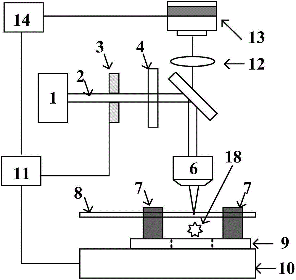
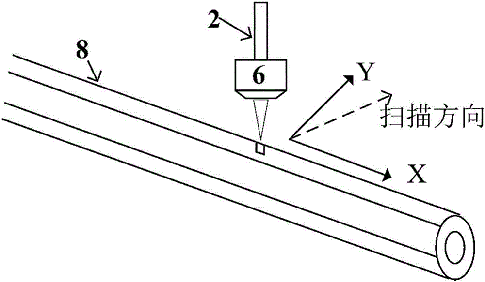
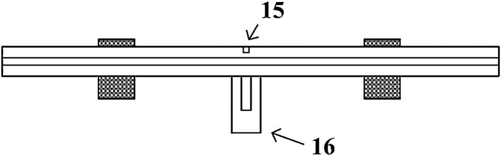
[0042] (1) Fix the optical fiber 8 on the electric translation platform 10, and fix it with a V-shaped optical fiber magnetic clamp 7;

[0043] (2) Select a microscopic objective lens 6 with 20× and a numerical aperture of 0.45, and under the auxiliary observation of the imaging lens 12 and the CCD detector 13, move the starting point of the optical fiber groove position to the focus position of the femtosecond laser 2 through the microscopic objective lens 6 At , adjust the three-dimensional electric translation stage 10 so that the top end of the optical fiber 8 is clearly imaged in the imaging system, and the coordinate of this position on the laser transmission axis Z-axis is defi...

Embodiment 2

[0048] Original material: solid core photonic crystal fiber;

[0049] Ultrashort pulse laser: 50fs, 800nm, 1000Hz;

[0050] (1) For the fixing of the optical fiber, refer to the corresponding process of Embodiment 1.

[0051] (2) For the relative position adjustment method of the optical fiber 8 and the focus point of the laser 2 , refer to the corresponding process of the first embodiment.

[0052] (3) Use the three-dimensional electric translation stage 10 to set the optical fiber 8 at a Z-axis position of 20 μm, and align the laser light to the starting point of the position to be grooved according to the scanning movement platform. The laser power was set at 2 mW, and the scanning speed was set at 100 μm / s. Open the optical shutter 3 to focus the femtosecond laser 2 on the optical fiber through the microscope objective lens. At the same time, the program controls the three-dimensional electric translation stage to drive the optical fiber to move along the axial direction...

Embodiment 3

[0056] Original material: hollow-core photonic crystal fiber;

[0057] Ultrashort pulse laser: 50fs, 800nm, 1000Hz;

[0058] (1) Fixing of the optical fiber 8 refers to the corresponding process of the first embodiment.

[0059] (2) For the relative position adjustment method of the optical fiber 8 and the focus point of the laser 2 , refer to the corresponding process of the first embodiment.

[0060] (3) Use the three-dimensional electric translation stage 10 to set the position of the optical fiber at the Z-axis to 20 μm, and align the laser with the starting point of the position to be grooved according to the scanning movement platform. The laser power was set to 1.5 mW, and the scanning speed was set to 100 μm / s. Open the optical shutter 3 to focus the femtosecond laser 2 on the optical fiber 8 through the microscopic objective lens 6. At the same time, the three-dimensional electric translation stage 10 is controlled by the program to drive the optical fiber 8 to move...


PUM


Abstract

Provided is an optical fiber cutting device and method based on ultra-short pulse lasers. The cutting device comprises an angle rotation platform arranged on a three-dimensional electric translation stage, an optical fiber is fixed on the angle rotation platform; the upper portion of the optical fiber is provided with a microobjective, a laser emitted from a laser device is reflected to the microobjective through a dichroscope, and the microobjective cuts the surface of the optical fiber after conducting focusing on the laser; the upper portion of the dichroscope is provided with an imaging lens and a CCD detector used for observing the focusing position of the microobjective; the laser device is provided with an optical shutter, the optical shutter and the three-dimensional electric translation stage are connected to a computer through a controller respetively, and an input end of the computer receives focusing position data observed by the CCD detector. The method comprises the steps of firstly forming a microgroove in the optical fiber, then exerting stress from the opposite face of the microgroove to make the optical fiber crack along the microgroove and completing cutting. The optical fiber cutting device based on the ultra-short pulse lasers is simple in structure, high in cutting precision and capable of achieving high-precision angle cutting.

Description

technical field [0001] The invention belongs to the field of optical fiber processing, and in particular relates to an optical fiber cutting device and cutting method based on ultrashort pulse laser. Background technique [0002] Fiber splicing or coupling is a key technology in fiber engineering applications, both of which require the fiber end face to be as smooth as possible. In addition, in order to reduce the reflection when coupling heterogeneous fibers, it is also necessary to cut the fiber at an angle. The most widely used optical fiber cleaving technology is to use mechanical cutters for cleaving. Due to the direct contact between the optical fiber and the tool in this method, it is easy to cause the cracking of the end face of the optical fiber. In particular, for the hollow-core photonic crystal fiber that has emerged in recent years, its structure is composed of periodic micro-holes, and the micro-hole structure on the end face is easily damaged by cutting with...

Claims


Application Information

Patent Timeline
Patent Type & Authority Applications(China)
IPC IPC(8): B23K26/382B23K26/082B23K26/03
CPCB23K26/03B23K26/082B23K26/382
Inventor 陈涛司金海李思佳杜勇闫理贺侯洵
Owner XI AN JIAOTONG UNIV
Why Eureka
Try Eureka