An infrared stealth device for exhaust mixed flow cooling of internal combustion engine power station

An internal combustion engine and mixed flow technology, which is applied to exhaust devices, mufflers, mechanical equipment, etc., can solve the problems of high exhaust temperature of internal combustion engine power plants, unfavorable use of military internal combustion engine power plants for stealth, and complex water tank structure.

Active Publication Date: 2019-05-03
JINAN JIMEILE POWER SUPPLY TECH
View PDF6 Cites 0 Cited by
  • Summary
  • Abstract
  • Description
  • Claims
  • Application Information

AI Technical Summary

Problems solved by technology

[0002] The exhaust temperature of the internal combustion engine power station is high, and the temperature difference with the surrounding environment is large, and the characteristics are obvious under the infrared detection condition, which is not conducive to the stealth use of the military internal combustion engine power station
At present, the measures to reduce the infrared characteristics of internal combustion engine power plants are mainly to use water-cooled mufflers to reduce the exhaust temperature. By using water-cooled mufflers to reduce the exhaust temperature, the purpose of reducing infrared characteristics can be achieved. Complicated, and the exhaust temperature cannot fully achieve the effect of infrared stealth

Method used


Image

  • An infrared stealth device for exhaust mixed flow cooling of internal combustion engine power station
  • An infrared stealth device for exhaust mixed flow cooling of internal combustion engine power station

Examples


Embodiment Construction

[0008] The present invention will be further described below in conjunction with accompanying drawings and examples.

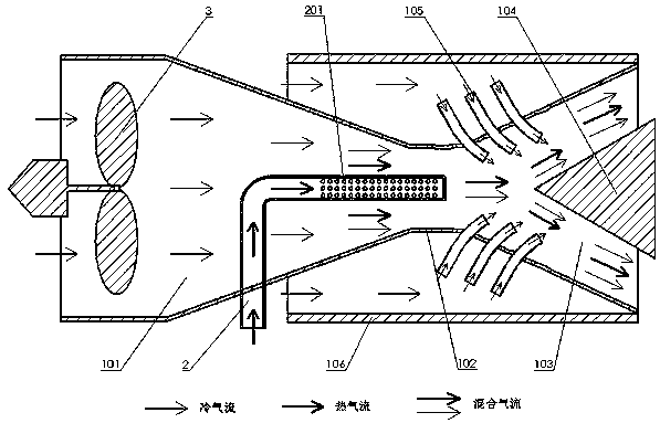
[0009] Such as figure 1 As shown, an infrared stealth device for exhaust mixed flow cooling of an internal combustion engine power station is characterized in that the device includes a mixed flow chamber 101, an acceleration throat 102, a horn-shaped expansion tail pipe 103, an exhaust diversion cone 104, a mixed flow nozzle 105, Insulation layer 106, muffler microporous exhaust tailpipe 2 and high-pressure fan 3, mixed flow chamber 101 is connected to trumpet-shaped expansion tailpipe 103 through accelerating throat pipe 102, muffler microporous exhaust tailpipe 2 is arranged in mixed flow chamber 101 At the center position, the high-pressure blower 3 is arranged at the entrance of the mixed flow chamber 101, the exhaust guide cone 104 is arranged at the outlet of the horn-shaped expansion tail pipe 103, and a plurality of mixed-flow nozzles 105 are arranged...


PUM


Abstract

The invention relates to an infrared stealth device for exhaust mixed flow cooling in an internal combustion engine power station, which is characterized in that: the mixed flow chamber (101) is connected to the trumpet-shaped expansion tailpipe (103) through the acceleration throat pipe (102), and the muffler microporous exhaust tailpipe (2) Arranged at the center of the mixed-flow chamber (101), the high-pressure fan (3) is arranged at the inlet of the mixed-flow chamber (101), and the exhaust guide cone (104) is arranged at the outlet of the horn-shaped expansion tailpipe (103). A mixed-flow nozzle (105) passes through the side wall of the flared flared tailpipe (103) and is arranged around the inlet of the flared flared tailpipe (103), and the mixed-flow nozzle (105) faces toward the outlet of the flared flared tailpipe (103), The heat insulation layer (106) is arranged on the outlet of the mixed flow chamber (101), the acceleration throat (102), the trumpet-shaped expansion tailpipe (103) and the periphery of the mixed flow nozzle (105). The ends of the expansion tail pipe (103) are connected in one piece. The invention reduces the exhaust gas temperature and helps the power station to realize infrared stealth.

Description

technical field [0001] The invention belongs to the technical field of internal-combustion engine power stations, and in particular relates to an infrared stealth device for exhaust mixed-flow cooling in an internal-combustion engine power station. Background technique [0002] The exhaust temperature of internal combustion engine power plants is relatively high, and the temperature difference with the surrounding environment is relatively large. The characteristics are obvious under infrared detection conditions, which is not conducive to the stealth use of military internal combustion engine power plants. At present, the measures to reduce the infrared characteristics of internal combustion engine power plants are mainly to use water-cooled mufflers to reduce the exhaust temperature. By using water-cooled mufflers to reduce the exhaust temperature, the purpose of reducing infrared characteristics can be achieved. It is complicated, and the exhaust temperature cannot fully ...

Claims


Application Information

Patent Timeline
Patent Type & Authority Patents(China)
IPC IPC(8): F01N3/05F01N13/14F01N13/20
CPCF01N3/05F01N13/14F01N13/20
Inventor 王怀杰张军刚谈学超刘海鹏白保健
Owner JINAN JIMEILE POWER SUPPLY TECH
Why Eureka
Try Eureka