Anticlockwise-tumble-ratio combustion system for automotive engine

A vehicle engine and combustion system technology, applied in combustion engines, machines/engines, internal combustion piston engines, etc., can solve the problems of flow dead zone, limiting the enhancement potential of direct injection engine in the cylinder, oil and gas enrichment knocking, etc. Reduce the tendency of knocking, increase the intensity of tumble flow in the cylinder, and reduce the effect of knocking

Inactive Publication Date: 2017-05-10
UNIV OF SHANGHAI FOR SCI & TECH
View PDF8 Cites 1 Cited by
  • Summary
  • Abstract
  • Description
  • Claims
  • Application Information

AI Technical Summary

Problems solved by technology

[0003] like figure 1 , as shown in 2 and 3, the combustion system of a traditional side-mounted direct-injection gasoline engine includes combustion chamber top 1., spark plug 2., cylinder centerline 3., fuel injector 4., intake valve stem 5., symmetrical intake air Door 6., Bottom surface of cylinder head 7., Cylinder wall 8., Piston 9., Counterclockwise tumble flow 10., Exhaust valve 11., Exhaust valve stem 12. Inlet port wall 18. Intake valve seat 22. , the traditional in-cylinder direct-injection gasoline engine adopts the arrangement of symmetrical intake valves 6, the angle 21 between the centerline of the intake port 19 and the centerline 20 of the intake valve seat circle is 35°~55°, matching the intake air of the injector The side injection and the top surface of the "roof-shaped" combustion chamber form an organized tumble flow that rotates counterclockwise in the combustion chamber, which accelerates the mixing process of injected fuel and air. Due to the dilution of lubricating oil caused by the contact of the cylinder wall, the organized counterclockwise tumble flow can be maintained until the late stage of the compression stroke, and it will be broken and transformed into turbulent kinetic energy to accelerate combustion at the moment of ignition; Sidestroke flow dead zone, resulting in the enrichment of oil and gas, which leads to the occurrence of knocking, which limits the enhancement potential of direct injection engines

Method used


Image

  • Anticlockwise-tumble-ratio combustion system for automotive engine
  • Anticlockwise-tumble-ratio combustion system for automotive engine
  • Anticlockwise-tumble-ratio combustion system for automotive engine

Examples


Embodiment Construction

[0015] The present invention will be further described below in conjunction with the accompanying drawings and embodiments.

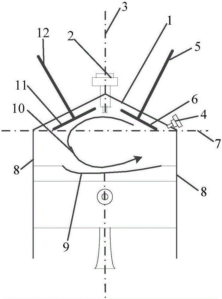
[0016] Such as Figure 4 , shown in 5 and 6, a vehicle engine reverse tumble ratio combustion system, including combustion chamber roof 1, cylinder wall 8, exhaust valve 11, exhaust valve stem 12, asymmetric intake valve stem 13, asymmetric Intake valve 14, exhaust side fuel injector 15, dimple piston 16, intake valve seat ring 22, vertical intake passage 26. Exhaust valve 11, exhaust side fuel injector 15, asymmetrical intake valve rod 13 and asymmetrical intake valve 14 are arranged on combustion chamber roof 1, and the center line of vertical air duct 26 is aligned with the center of intake valve seat ring. Line angle 24 is 15°~25°, combustion chamber top 1, spark plug 2, cylinder wall 8, pit piston 16, exhaust side injector 15, intake valve seat 22, exhaust valve 11, exhaust The door lever 12 forms a reverse tumble ratio combustion system that org...


PUM


Abstract

The invention relates to an anticlockwise-tumble-ratio combustion system for an automotive engine. The anticlockwise-tumble-ratio combustion system comprises a combustion chamber roof, a cylinder wall, an exhaust valve, a pit piston, an exhaust-side oil sprayer, an intake valve seat ring and a vertical intake channel, wherein the exhaust valve, the exhaust-side oil sprayer, an asymmetrical intake valve rod and an asymmetrical intake valve are arranged on the combustion chamber roof; the included angle between the central line of the vertical intake channel and the central line of the intake valve seat ring is 15-25 degrees; fresh air enters through the vertical intake channel, and more gases flow towards the right under the action of the asymmetrical intake valve, collide with the pit piston to be reflected, and form serious clockwise rotating tumble in a cylinder through the guide of the cylinder wall and the combustion chamber roof, for improving flowing at the exhaust side, reducing a detonation trend and accelerating combustion. The anticlockwise-tumble-ratio combustion system disclosed by the invention is capable of effectively reducing the detonation of a lateral direct-injection gasoline engine in the cylinder, improving the strength of the tumble in the cylinder, and accelerating the combustion.

Description

technical field [0001] The invention relates to a vehicle engine combustion system, in particular to a vehicle engine reverse tumble ratio combustion control system. Background technique [0002] In-cylinder direct injection technology for automotive gasoline engines can effectively increase the power per liter of the engine and reduce the fuel consumption and emissions of the vehicle. It is a common combustion control technology in the field of automotive engines. Due to the direct fuel injection in the cylinder, the mixing time of gasoline and air is greatly shortened, so it is necessary to organize regular airflow movement in the cylinder to ensure the uniform and ideal distribution of the mixture of oil and gas in the cylinder at the moment of ignition. Developing a reasonable in-cylinder airflow movement organization mode to improve the fuel efficiency of side-mounted direct-injection engines and reduce emissions has always been the goal pursued in the field of direct-i...

Claims


Application Information

Patent Timeline
Patent Type & Authority Applications(China)
IPC IPC(8): F02B23/10F02B31/02
CPCF02B23/10F02B31/02F02B2023/107Y02T10/12
Inventor 沈凯张振东王小燕袁贤良
Owner UNIV OF SHANGHAI FOR SCI & TECH
Why Eureka
Try Eureka