Intake manifold that directs crankcase ventilation gases

A technology for crankcase ventilation and intake manifold, which is applied in the directions of fuel air intake, combustion air/combustion-air treatment, charging system, etc. icing problems

Active Publication Date: 2019-05-03
GUANGZHOU AUTOMOBILE GROUP CO LTD
View PDF7 Cites 0 Cited by
  • Summary
  • Abstract
  • Description
  • Claims
  • Application Information

AI Technical Summary

Problems solved by technology

In addition, in order to meet the increasingly stringent emission requirements and improve the economy, the crankcase ventilation system must also be designed in the design process of the automobile engine, so that the airflow of the crankcase is introduced into the engine cylinder for re-combustion, but in the cold area (such as -10 ℃ ~-30℃), because the intake air temperature in the intake manifold is low, tens of degrees below zero, after the crankcase ventilation gas is mixed with the low-temperature gas, the temperature drops, even below zero, and the crankcase ventilation gas contains Water vapor will condense into water droplets or even freeze, which will freeze the throttle valve, block the curved pipe or block the intake pipe, and affect the normal operation of the engine

Method used


Image

  • Intake manifold that directs crankcase ventilation gases
  • Intake manifold that directs crankcase ventilation gases
  • Intake manifold that directs crankcase ventilation gases

Examples


Embodiment Construction

[0017] In order to make the purpose, technical solution and advantages of the present invention clearer, the embodiments of the present invention will be further described below in conjunction with the accompanying drawings.

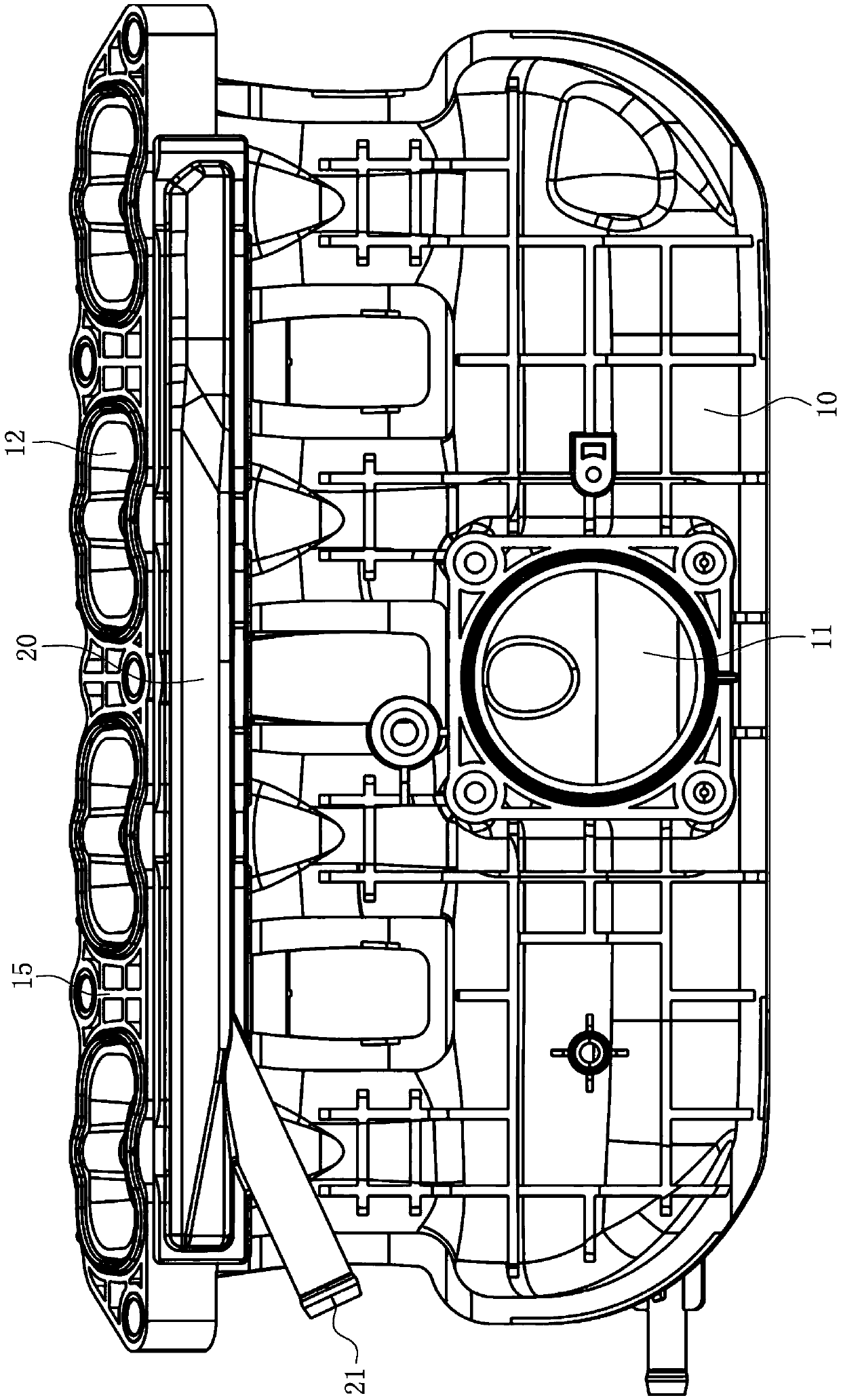
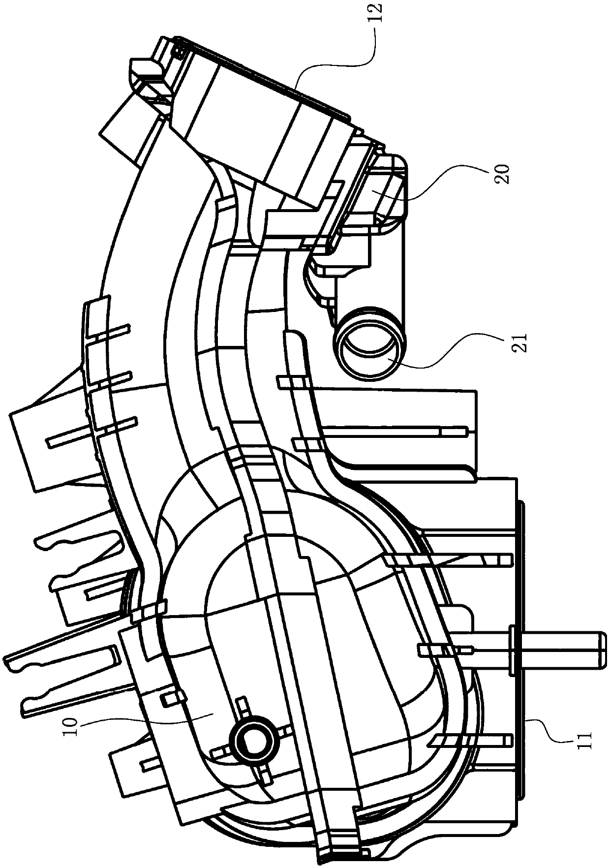
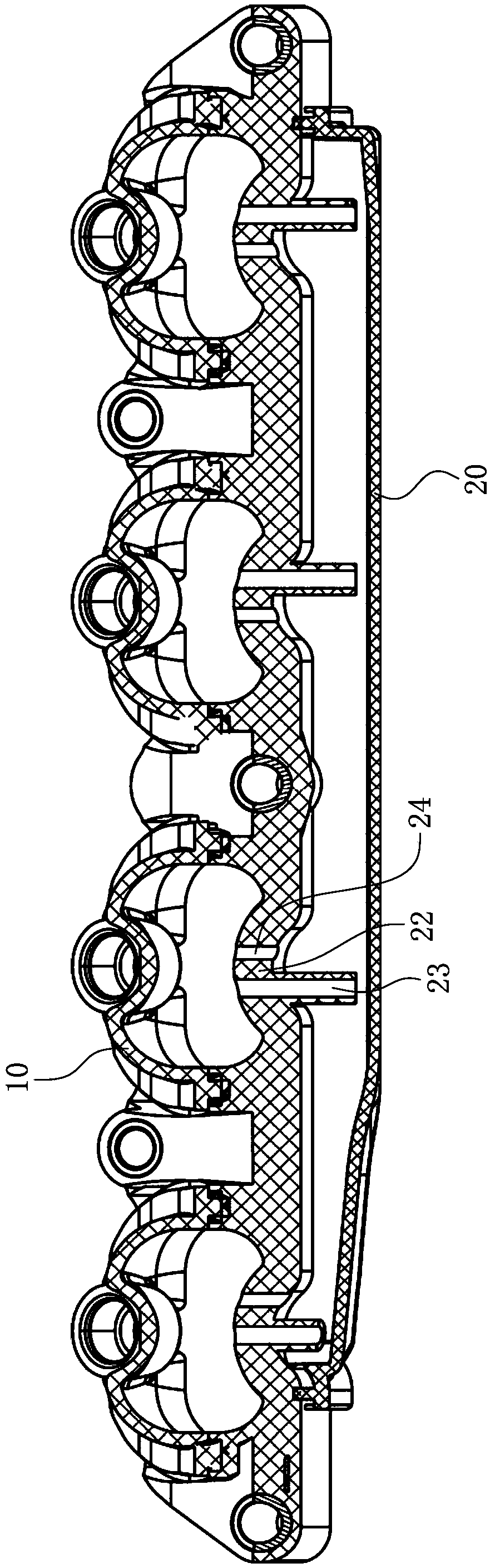
[0018] Please also refer to Figure 1 to Figure 3 , the present invention provides a kind of intake manifold 10 that can guide the crankcase ventilation gas, used to introduce the crankcase ventilation gas into the engine cylinder, the intake manifold includes an air inlet 11, a flange surface 15 and a plurality of The air outlet 12 on the flange surface 15, each air outlet 12 is respectively communicated with a cylinder of the engine and supplies gas to it, the air outlet 12 is located on the upper part of the air inlet 11, and the gas flowing in from the air inlet 11 is The intake manifold 10 runs upwards and flows from the airflow outlet 12 into the cylinders of the engine.

[0019] The intake manifold 10 also includes a crankcase ventilation gas aux...


PUM


Abstract

The invention provides an intake manifold capable of guiding ventilation gas of a crankcase. The intake manifold comprises a gas flow inlet, a flange face and multiple gas flow outlets located in the flange face. Each gas flow outlet communicates with an air cylinder of an engine and supplies gas to the air cylinder communicating with the gas flow outlet. The intake manifold further comprises a crankcase ventilation gas auxiliary cavity located in the lower side of the flange face. The crankcase ventilation gas auxiliary cavity comprises a crankcase ventilation gas inlet, a first connecting hole and a second connecting hole. The second connecting hole is higher than the first connecting hole, the first connecting hole and the second connecting hole communicate with the gas flow outlets, and the ventilation gas of the crankcase flows into the crankcase ventilation gas auxiliary cavity through the crankcase ventilation gas inlet. Due to the high temperature of the flange face, condensation of the ventilation gas of the crankcase is reduced. The first connecting hole and the second connecting hole are used for guiding the ventilation gas of the crankcase into the corresponding gas flow outlets.

Description

technical field [0001] The invention relates to an air intake device of an engine, in particular to an intake manifold capable of guiding crankcase ventilation gas. Background technique [0002] When the engine is working, the high-pressure combustible mixture and burned gas in the combustion chamber will more or less leak into the crankcase through the gap between the piston group and the cylinder, causing blow-by. The components of blow-by gas are unburned fuel gas, water vapor and exhaust gas, etc., which will dilute the engine oil, reduce the performance of the engine oil, and accelerate the oxidation and deterioration of the engine oil. Moisture condenses in the engine oil, which will form sludge and block the oil circuit; the acid gas in the exhaust gas will be mixed into the lubrication system, which will cause corrosion and accelerated wear of engine parts; blow-by gas will also cause the pressure of the crankcase to be too high and damage the crankcase. Sealed to a...

Claims


Application Information

Patent Timeline
Patent Type & Authority Patents(China)
IPC IPC(8): F02M35/10F02M35/104
CPCF02M35/10222F02M35/104
Inventor 黄英铭陈良刘巨江占文锋朱晨虹
Owner GUANGZHOU AUTOMOBILE GROUP CO LTD
Why Eureka
Try Eureka