
Speed reducer for solar thermal electric power generation

A technology of photothermal power generation and reducer

Inactive Publication Date: 2017-05-10
苏州吾纳德传动技术有限公司
View PDF6 Cites 2 Cited by
  • Summary
  • Abstract
  • Description
  • Claims
  • Application Information

AI Technical Summary

Problems solved by technology

At present, the structure of the reducer used in photothermal power generation is complicated, the number of parts is large, the transmission error is large, and the rigidity is small, which causes the mirror to shake during the rotation process and after a period of rotation, the alignment angle between the mirror and the sun has a large deviation. Seriously affect power generation efficiency

Method used


Image

  • Speed reducer for solar thermal electric power generation

Examples


Embodiment Construction

[0021] The following will clearly and completely describe the technical solutions in the embodiments of the present invention with reference to the drawings in the embodiments of the present invention.

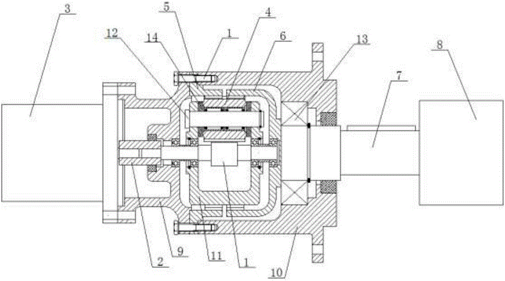
[0022] The invention provides a reducer for photothermal power generation. Its working principle is to drive the planetary gear through the input shaft gear, and then drive the output shaft to rotate through the first inner ring gear and the second inner ring gear, so as to convert the high speed of the motor into The face-changing movement of the mirror makes the angular rate of rotation of the mirror conform to the angular rate of movement of the sun, and the coaxial rotation of the input shaft and the output shaft is realized by using the input shaft gear, the first internal ring gear and the second internal ring gear to increase the speed ratio The optional range, reduce the number of parts, reduce the difficulty of processing, ensure the transmission accuracy and ensure th...


PUM


Abstract

The invention discloses a speed reducer for solar thermal electric power generation. The speed reducer comprises a box, an input shaft gear is arranged in the box and can be connected with an external motor through a coupler, the input shaft gear is connected with a planet gear which is in meshed connection with a first inner gear ring and a second inner gear ring, and an output shaft is fixedly connected to the second inner gear ring and connected with an external working machine. The planet gear is driven by the input shaft gear, and the output shaft is driven to rotate through the first inner gear ring and the second inner gear ring so as to convert high rotation speed of the motor into plane change movement of mirror planes to make rotation angular rate of the mirror planes accord with solar moving angular rate. Coaxial rotation of an input shaft and the output shaft is realized by the input shaft gear, the first inner gear ring and the second inner gear ring, and widening of a speed ratio selectable range, reduction of parts, lowering of machining difficulty and guarantee of transmission precision and power generation efficiency are realized.

Description

technical field [0001] The invention relates to a speed reducer, in particular to a speed reducer for photothermal power generation. Background technique [0002] Photothermal power generation uses mirrors to collect solar energy, and then provides steam through a heat exchange device, and the steam drives a turbo generator to generate electricity. It is a type of clean energy. When the mirror collects solar energy, the mirror needs to be always aligned with the sun at a certain angle, which requires the mirror to move according to the movement of the sun. At present, the structure of the reducer used in photothermal power generation is complicated, the number of parts is large, the transmission error is large, and the rigidity is small, which causes the mirror to shake during the rotation process and after a period of rotation, the alignment angle between the mirror and the sun has a large deviation. Seriously affect the power generation efficiency. Contents of the inven...

Claims


Application Information

Patent Timeline
Patent Type & Authority Applications(China)
IPC IPC(8): F16H1/32F16H57/023F16H57/08
CPCF16H1/32F16H57/023F16H2001/2872F16H2001/2881F16H2057/085
Inventor 袁包钢陈晓爱杨定辉张磊磊
Owner 苏州吾纳德传动技术有限公司
Learn More