Coil type heat exchanger

A heat exchanger and coil type technology, applied in the field of heat exchange, can solve the problems of insignificant economic benefit of heat recovery, easy blockage of the heat exchanger flow channel, large temperature difference at the hot end of the heat exchanger, etc., and achieves a small occupied space. , The effect of strong pressure bearing capacity and sufficient heat exchange

Inactive Publication Date: 2017-05-10
刘洋豪
View PDF2 Cites 0 Cited by
  • Summary
  • Abstract
  • Description
  • Claims
  • Application Information

AI Technical Summary

Problems solved by technology

[0002] In daily life and industrial production, in order to improve the heat exchange efficiency of the heat exchanger, the diameter of the flow channel of the heat exchanger should be made as small as possible. The flow channel is easily blocked; at the same time, the flow channel of the heat exchanger is short, and the temperature difference at the hot end of the heat exchanger is large (the temperature difference at the hot end refers to the temperature difference between when the hot medium flows into the heat exchanger and when the cold medium flows out of the heat exchanger), and the heat recovery efficiency is low , the economic benefits of heat recovery are not significant, and the problem of recycling waste hot water heat in household baths, beauty salons, large bathing centers and industrial production has not been well resolved.

Method used


Image

  • Coil type heat exchanger

Examples


Embodiment Construction

[0016] The present invention will be further described below in conjunction with accompanying drawing.

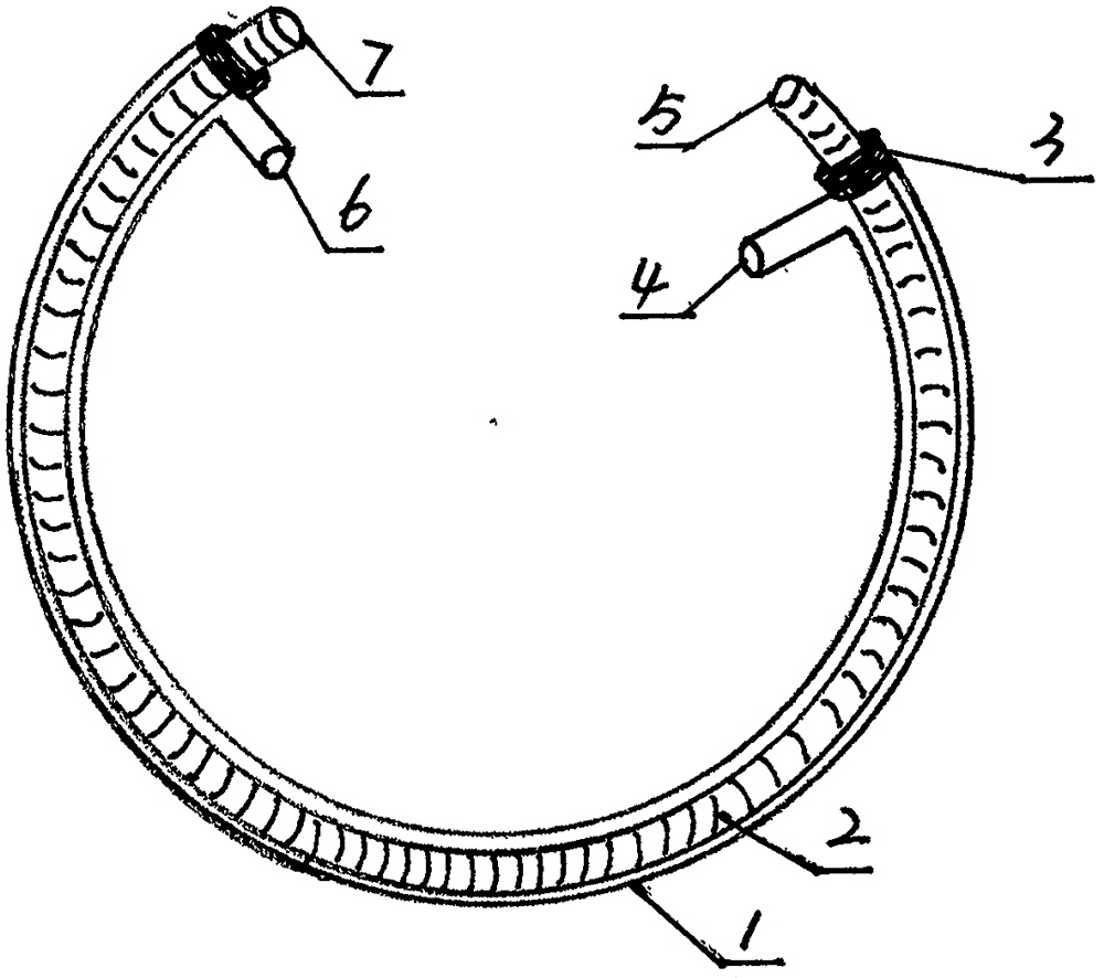
[0017] A coiled tube heat exchanger according to the present invention comprises a coiled tube 1 and a metal bellows 2, and is characterized in that: a metal bellows 2 is installed in the coiled tube 1, and the two ends of the metal bellows 2 The openings are exposed outside the openings at both ends of the coil tube 1, and the openings at both ends of the coil tube 1 and the outer wall of the metal bellows 2 are sealed by injection molding, hot melting, welding or colloid. The other end of the metal bellows 2 is equipped with a second interface 6, one end of the metal bellows 2 is opened as the third interface 7, and the other end of the metal bellows 2 is opened as the fourth interface 5, the cavity space between the inner wall of the coil 1 and the outer wall of the metal bellows 2 and The first interface 4 and the second interface 6 form the first flow channel, and the ...


PUM

PropertyMeasurementUnit
lengthaaaaaaaaaa
diameteraaaaaaaaaa

Abstract

The invention provides a coil type heat exchanger. The coil type heat exchanger comprises a coil and a metal corrugated pipe. The coil type heat exchanger is characterized in that the metal corrugated pipe with the large caliber is mounted in the coil, openings in the two ends of the metal corrugated pipe are exposed out of openings in the two ends of the coil, and the openings in the two ends of the coil and the outer wall of the metal corrugated pipe are sealed through injection molding, hot melting, welding or colloid; a first joint is mounted at one end of the coil, a second joint is mounted at the other end of the coil, a third joint is the opening in one end of the metal corrugated pipe, and a fourth joint is the opening in the other end of the metal corrugated pipe; the metal corrugated pipe is a copper corrugated pipe or a stainless steel corrugated pipe; and the coil is a rubber coil or a plastic coil. According to the coil type heat exchanger, the runner is long, the metal corrugated pipe with the large caliber is used for flowing of waste hot water, blocking is not likely to happen, the heat exchange efficiency is high, and the coil type heat exchanger can be widely applied to recovery of waste hot water and hot energy generated in household bathing, hairdressing and beauty, large bath centers and industrial production.

Description

technical field [0001] The invention relates to the field of heat exchange, in particular to a coil heat exchanger. Background technique [0002] In daily life and industrial production, in order to improve the heat exchange efficiency of the heat exchanger, the diameter of the flow channel of the heat exchanger should be made as small as possible. The flow channel is easily blocked; at the same time, the flow channel of the heat exchanger is short, and the temperature difference at the hot end of the heat exchanger is large (the temperature difference at the hot end refers to the temperature difference between when the hot medium flows into the heat exchanger and when the cold medium flows out of the heat exchanger), and the heat recovery efficiency is low However, the economic benefits of heat recovery are not significant, and the problem of recovering waste hot water heat in household baths, beauty salons, large bath centers and industrial production has not been well res...

Claims


Application Information

Patent Timeline
Patent Type & Authority Applications(China)
IPC IPC(8): F28D7/10F28F21/06F28F21/08F28F1/08
CPCF28D7/10F28F1/08F28F21/06F28F21/083F28F21/085
Inventor 刘洋豪刘兴波
Owner 刘洋豪
Why Eureka
Try Eureka