Laser projection system

A laser projection and laser technology, applied in the field of projection display, can solve problems such as dizziness and discomfort, reduce user viewing experience, and degradation of projected image quality, and achieve the effect of improving the effect of eliminating speckle and eliminating speckle effect

Inactive Publication Date: 2017-05-10
HISENSE
View PDF7 Cites 16 Cited by
  • Summary
  • Abstract
  • Description
  • Claims
  • Application Information

AI Technical Summary

Problems solved by technology

[0003] The high coherence of laser also brings the speckle effect in laser projection display. Speckle is that when a coherent light source irradiates a rough object, the scattered light will interfere in space because of its same wavelength and constant phase. Some parts of the space have interference and constructive effects, and some parts hav

Method used


Image

  • Laser projection system
  • Laser projection system
  • Laser projection system

Examples


Embodiment 1

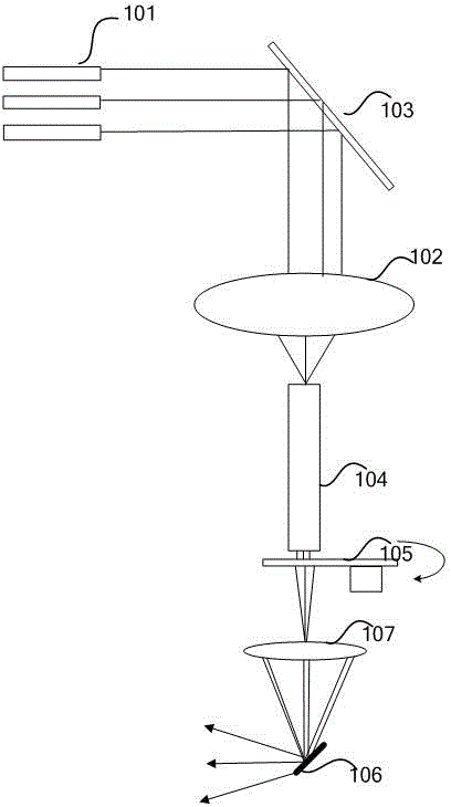
[0046] See Figure 1A , Is a schematic diagram of the optical architecture of laser projection provided by the embodiment of the application.

[0047] The optical architecture of a laser projection system provided in an embodiment of the present invention includes: a laser 101, a vibrating reflective phase plate 103, a converging lens 102, a light homogenizing component 104, a moving diffuser 105, a converging lens 107, and a light valve 106 .

[0048] Laser beam at Figure 1A The transmission path in the optical architecture shown is as follows:

[0049] The laser beam emitted by the laser 101 enters the vibrating reflective phase plate 103. In the above process, the laser beam emitted by the laser 101 usually requires some collimating or converging parts to form a smaller spot and enters the vibrating reflective phase plate 103. Figure 1A Not shown in.

[0050] After being reflected by the vibrating reflective phase plate 103, the laser beam is condensed and compressed by the condensi...

Embodiment 2

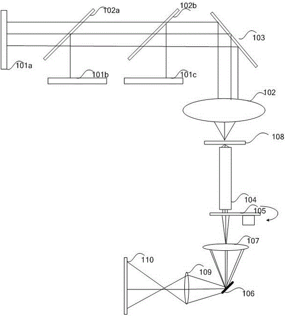
[0079] And as Figure 1A Variants such as Figure 1B As shown, on the light incident surface side of the light rod 104, specifically, a first phase plate 108 is also provided between the vibrating mirror 103 and the light entrance port of the light rod 104. In this example, the first phase plate 108 may specifically be a transmissive phase plate and is fixedly arranged.

[0080] in Figure 1B The shown laser projection system specifically includes: a laser 101a, a laser 101b, and a laser 101c, respectively emitting laser beams, a first combining lens 102a, and a second combining lens 102b. The laser beams emitted by the above laser pass through these two The light combining lens combines light to form a beam of light output. In practical applications, the lasers 101a, 101b, and 101c can be specifically blue laser 101a, red laser 101b, green laser 101c, first light combining lens 102a can be specifically dichroic plate 102a, and second light combining lens 102b can be specifically ...


PUM


Abstract

The invention discloses a laser projection system, comprising a laser light source which is used for emitting laser beams of at least one color; a light homogenization component which is used for receiving and homogenizing the laser beams; a light valve which is used for receiving the laser beams homogenized by the light homogenization component and modulating the laser beams; a vibrating reflection-type phase plate which is arranged on a light incident surface side of the light homogenization component; and a motion diffuser which is arranged on a light emergent surface side of the light homogenization component. A position at which the motion diffuser is located is an object plane position of the light valve. The number of produced random phases can be greatly increased, according to the random phases, through integral action of human eyes, the speckle effect of a projection image can be reduced or eliminated to the greatest extent, and the speckle eliminating effect and the display quality of the projection image can be greatly improved.

Description

Technical field [0001] This application relates to the field of projection display, and in particular to a laser projection system. Background technique [0002] Laser is a light source with high brightness, strong directivity, and monochromatic coherent beam. As an excellent coherent light source, laser light source has the advantages of good monochromaticity, strong directivity and high luminous flux. In recent years, it has gradually been used as a light source Projection display technology field. [0003] The high coherence of the laser also brings about the speckle effect during laser projection display. Speckle is that when a coherent light source illuminates a rough object, the scattered light will interfere in space due to the same wavelength and constant phase. Some parts of the space interfere constructively and some parts interfere. The final result is granular bright and dark spots on the screen. These unfocused spots appear to be flickering to the human eye, and they ...

Claims


Application Information

Patent Timeline
IPC IPC(8): G03B21/20G02B27/48
CPCG03B21/2033G02B27/48G03B21/2013G03B21/206G03B21/208
Inventor 田有良李巍刘显荣
Owner HISENSE
Why Eureka
Try Eureka