
Machine tool vibration monitoring system and method based on LabView and single chip microcomputer

A vibration monitoring system and single-chip technology, applied in the field of machine tool vibration monitoring, can solve problems such as single function, aggravated vibration, and difficulty in realizing vibration prediction, and achieve the effects of optimizing machining parameters, improving machined surface quality, and reducing machine tool machining vibrations.

Pending Publication Date: 2017-05-10
SHENYANG MASCH TOOL CO LTD
View PDF9 Cites 2 Cited by
  • Summary
  • Abstract
  • Description
  • Claims
  • Application Information

AI Technical Summary

Problems solved by technology

[0002] Machine tool machining vibration is an important factor affecting the surface quality of the workpiece. During the machining process of CNC machine tools, the contact surface between the tool and the workpiece rotates with the spindle to generate vibration excitation on the machine tool, and due to factors such as machine tool assembly, workpiece clamping and processing technology, vibration prediction It is difficult to realize. After the machining program is compiled and run, the machining parameters are fixed during the machining process, so the machine tool cannot respond to unexpected situations during the machining process, such as tool collision, increased vibration, etc.
[0003] A machine tool vibration online monitoring system with the patent number CN201420471749.X monitors and controls the spindle through the CNC system of the machine tool, and requires the CNC system to open corresponding permissions to it, and has a single function, which can only realize the alarm function
[0004] A machine tool vibration sensor monitoring device with patent number CN201320505108.7 and a machine tool operation monitoring system with patent number CN201120096755.8 can only collect vibration signals and cannot make the machine tool respond automatically

Method used


Image

  • Machine tool vibration monitoring system and method based on LabView and single chip microcomputer
  • Machine tool vibration monitoring system and method based on LabView and single chip microcomputer
  • Machine tool vibration monitoring system and method based on LabView and single chip microcomputer

Examples


Embodiment Construction

[0038] The present invention will be further elaborated below in conjunction with the accompanying drawings of the description.

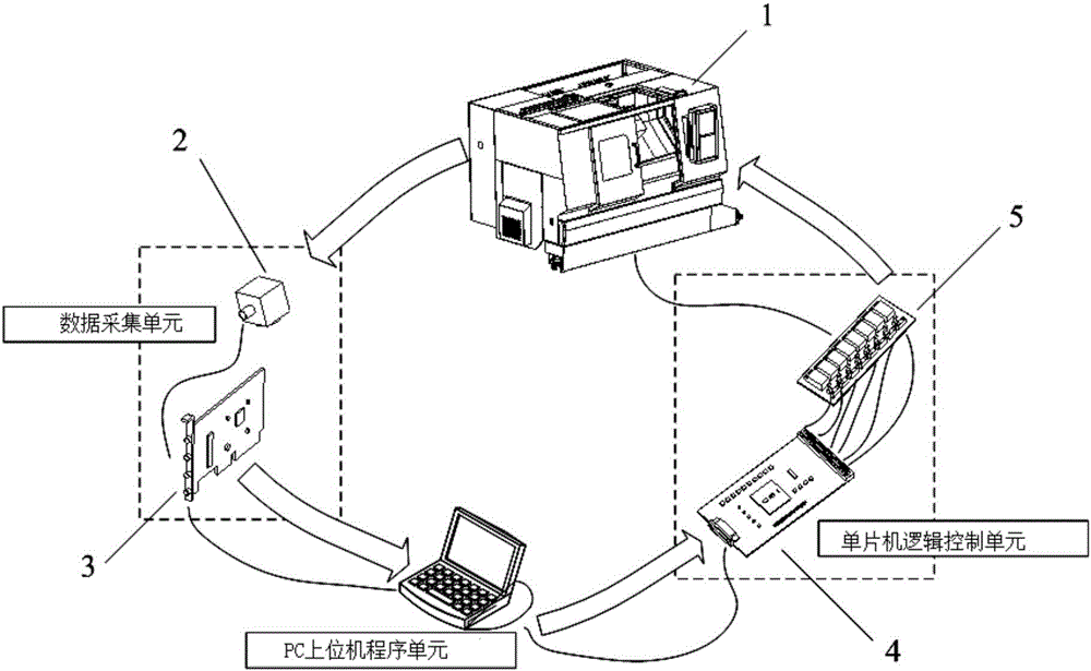
[0039] Such as figure 1 As shown, a kind of machine tool vibration monitoring system based on LabView and single-chip microcomputer of the present invention has data acquisition unit, PC upper computer program unit and single-chip computer logic control unit, wherein: the vibration data of data acquisition unit acquisition machine tool 1 is imported into PC upper computer program unit; PC upper computer program unit analyzes and calculates the vibration data of the machine tool, and outputs control instructions to the logic control unit of the single chip; Stop processing the signal, and the PLC program of the machine tool writes the signal into the designated memory for machine tool system operation.

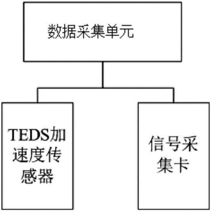
[0040] Such as figure 2 As shown, the PC upper computer program unit includes a TEDS sensor automatic detection module, a signal display module, ...


PUM


Abstract

The invention relates to a machine tool vibration monitoring system and a method based on LabView and a single chip microcomputer. The system comprises a data acquisition unit, a PC upper computer program unit and a single chip microcomputer logic control unit, wherein the data acquisition unit acquires machine tool vibration data and the machine tool vibration data are transmitted to the PC upper computer program unit; the PC upper computer program unit analyzes and calculates the machine tool vibration data, and a control instruction is outputted to the single chip microcomputer logic control unit; and the single chip microcomputer logic control unit carries out logic processing on the control instruction to transmit spindle speed ratio change, feeding ratio change and sudden stop processing signals to the machine tool PLC. Acquisition and analysis of machine tool cutting vibration data and generation of a report are facilitated, an expensive vibration analyzer can be replaced, program adjustment according to requirements of a company can be carried out, link with a CNAS detection standard is efficient, and through carrying out simple wiring and changing a tiny small part of PLC programs only, dynamic control on the machine tool spindle and the feeding can be realized.

Description

technical field [0001] The invention relates to a machine tool vibration monitoring technology, in particular to a machine tool vibration monitoring system and method based on LabView and a single-chip microcomputer. Background technique [0002] Machine tool machining vibration is an important factor affecting the surface quality of the workpiece. During the machining process of CNC machine tools, the contact surface between the tool and the workpiece rotates with the spindle to generate vibration excitation on the machine tool, and due to factors such as machine tool assembly, workpiece clamping, and processing technology, vibration prediction It is difficult to realize. After the machining program is compiled and run, the machining parameters are fixed during the machining process, so the machine tool cannot respond to unexpected situations during the machining process, such as tool collision and increased vibration. [0003] A machine tool vibration online monitoring sys...

Claims


Application Information

Patent Timeline
Patent Type & Authority Applications(China)
IPC IPC(8): G05B19/406
CPCG05B19/406G05B19/4061Y02P90/02
Inventor 林剑峰邬铎曹文智王凯谭智刘阔姜宇
Owner SHENYANG MASCH TOOL CO LTD
Learn More