Reactor core water injection evaluation method for nuclear power plant equipped with reactor core catcher

A technology of core capture and evaluation method, which is applied in the field of core water injection evaluation of nuclear power plants, can solve problems such as changes, and achieve the effects of avoiding steam explosions, improving severe accident management, and improving monitoring and status diagnosis

Active Publication Date: 2017-05-10
NUCLEAR POWER INSTITUTE OF CHINA
View PDF4 Cites 14 Cited by
  • Summary
  • Abstract
  • Description
  • Claims
  • Application Information

AI Technical Summary

Problems solved by technology

Relocation of core melt after a severe accident will cause changes in the neutron flux data outside the pressure vessel

Method used


Image

  • Reactor core water injection evaluation method for nuclear power plant equipped with reactor core catcher
  • Reactor core water injection evaluation method for nuclear power plant equipped with reactor core catcher
  • Reactor core water injection evaluation method for nuclear power plant equipped with reactor core catcher

Examples


Embodiment 1

[0092] A pressurized water reactor nuclear power plant is equipped with a crucible-type core trap specially for severe accidents. The power plant has arranged a large number of passive hydrogen recombiners in the containment for the threat of hydrogen in severe accidents. Therefore, the threat of hydrogen is not the main serious accident of the plant. The threat of accidents, the negative impact of hydrogen generation will not be considered in the analysis of core water injection countermeasures.

[0093] Similar to the scene of the Fukushima accident, after the tsunami, the entire plant was powered off, and the special safety facilities could not be activated. After the power outage, the power plant stopped unnecessary power consumption such as lighting, and the battery power was maintained for a long time. The main control room can still grasp the key points. Instrument monitoring data. After the core is exposed, it is monitored that the core outlet temperature exceeds 650°C...

Embodiment 2

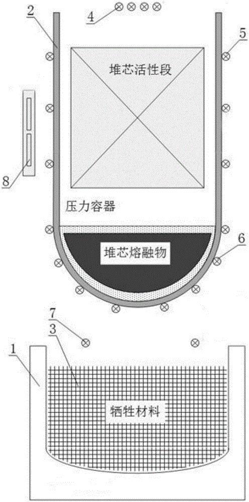
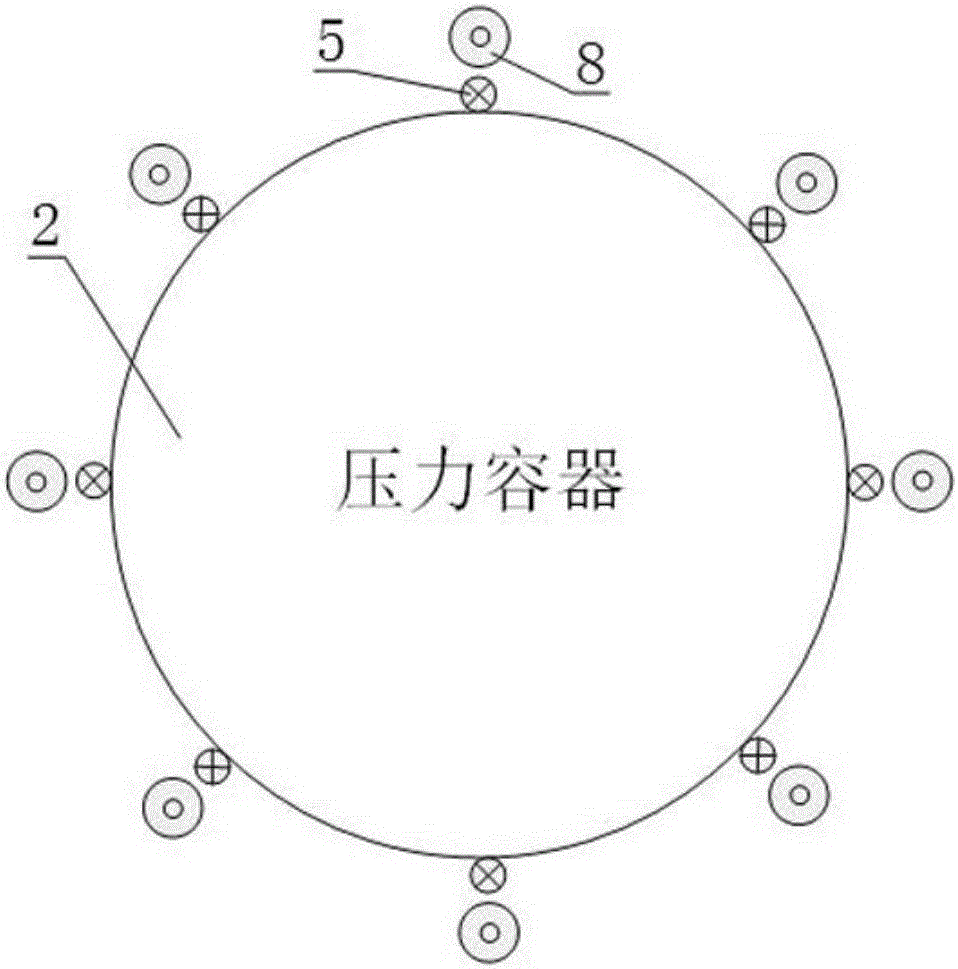
[0106] The configuration of the power plant is roughly the same as that of Example 1. On the basis of Example 1, the design of the power plant has been improved for monitoring the temperature outside the pressure vessel. Several high-range thermocouples are installed in the insulation layer close to the outer wall of the pressure vessel. These thermocouples Evenly distributed at different angles in the circumferential direction of the pressure vessel, and thermocouples are arranged vertically from the height of the active section of the core to the bottom of the lower head, such as figure 1 , figure 2 shown. In terms of signal transmission, a temperature signal transmission channel is added on the basis of the original external nuclear test signal channel, and finally the main control room can monitor the temperature of the outer wall of the pressure vessel.

[0107] After the earthquake, a large breach accident occurred, the double ends of the main pipeline were sheared and...


PUM


Abstract

The invention discloses a reactor core water injection evaluation method for a nuclear power plant equipped with a reactor core catcher. The method comprises the following steps that S1, a reactor core melting process in a pressure container is simplified to three stages; and S2, in combination with a specific reactor core melting process, the water injection evaluation method comprises the following sub-steps of S21, monitoring a process of relocating reactor core molten debris in the pressure container, judging a state of reactor core melting according to instrument monitoring data, and performing analysis in combination with a specific reactor core state to determine a reactor core water injection strategy; S22, monitoring a cooling effect of reactor core water injection, and further adjusting the reactor core water injection strategy; S23, when melt-through of a lower seal head of the pressure container is monitored, stopping water injection; and S24, monitoring melt-through scale and duration of the pressure container, and performing reactor core water injection according to actual position and state of the reactor core molten debris. The method has the beneficial effects that different water injection strategies are given in different accident stages; the water injection flow is controlled according to the cooling effect, so that steam explosion is avoided; and resources are reasonably utilized.

Description

technical field [0001] The invention relates to the technical field of severe accident management of nuclear power plants, in particular to a core water injection evaluation method of a nuclear power plant equipped with a core catcher. Background technique [0002] After a severe accident, the core is damaged, melted and relocated to the lower head of the pressure vessel. The core melt may melt through the lower head of the pressure vessel. The failure of the pressure vessel will lead to many adverse consequences, for example, it is difficult to maintain the core melt The continuous cooling of radioactive fission products diffuses completely into the containment vessel, threatening the integrity of the containment vessel, etc. Therefore, some advanced nuclear power plants set up a core trap under the pressure vessel, and the lower head of the pressure vessel melts and falls into the core trap to continue cooling the melt. [0003] Usually, water is injected into the core tr...

Claims


Application Information

Patent Timeline
Patent Type & Authority Applications(China)
IPC IPC(8): G06Q10/06G06Q50/06G21C15/18G21C17/022G21D3/06
CPCG06Q10/0635G06Q50/06G21C15/182G21C17/022G21D3/06Y02A10/40Y02E30/00Y02E30/30
Inventor 孔翔程黄代顺邓坚向清安陈彬刘丽莉邹志强
Owner NUCLEAR POWER INSTITUTE OF CHINA
Why Eureka
Try Eureka